1. Install the Arduino IDE
Download the latest version of the Arduino IDE from the official website.
Install it on your computer.
2. Install ESP32 Board Package
Open the Arduino IDE.
Go to File > Preferences.
In the “Additional Boards Manager URLs” field, add this URL: https://dl.espressif.com/dl/package_esp32_index.json.
Go to Tools > Board > Boards Manager.
Search for ESP32 and install the package for ESP32 boards by Espressif Systems.
3. Connect ESP32 to Your Computer
Use a micro USB cable to connect the ESP32 to your computer.
In the Arduino IDE, go to Tools > Port and select the port that your ESP32 is connected to.
4. Install the Required Libraries
You need the Servo library for this project. Go to Sketch > Include Library > Manage Libraries.Search for Servo and install it.
5. Modify the Wi-Fi Credentials in Your Code
Replace the placeholder xxxxxxx in const char* ssid and const char* password with your actual Wi-Fi name and password.
6.Upload the Code to ESP32
Copy the provided code into the Arduino IDE.
Select your ESP32 board by going to Tools > Board > and choosing ESP32 Dev Module.
Click the Upload button (the arrow pointing right) to upload the code to your ESP32.
7.Monitor Serial Output
After uploading, open the Serial Monitor from Tools > Serial Monitor or by pressing Ctrl+Shift+M.
Set the baud rate to 115200.
You should see messages showing the connection status of the ESP32 to your Wi-Fi network.
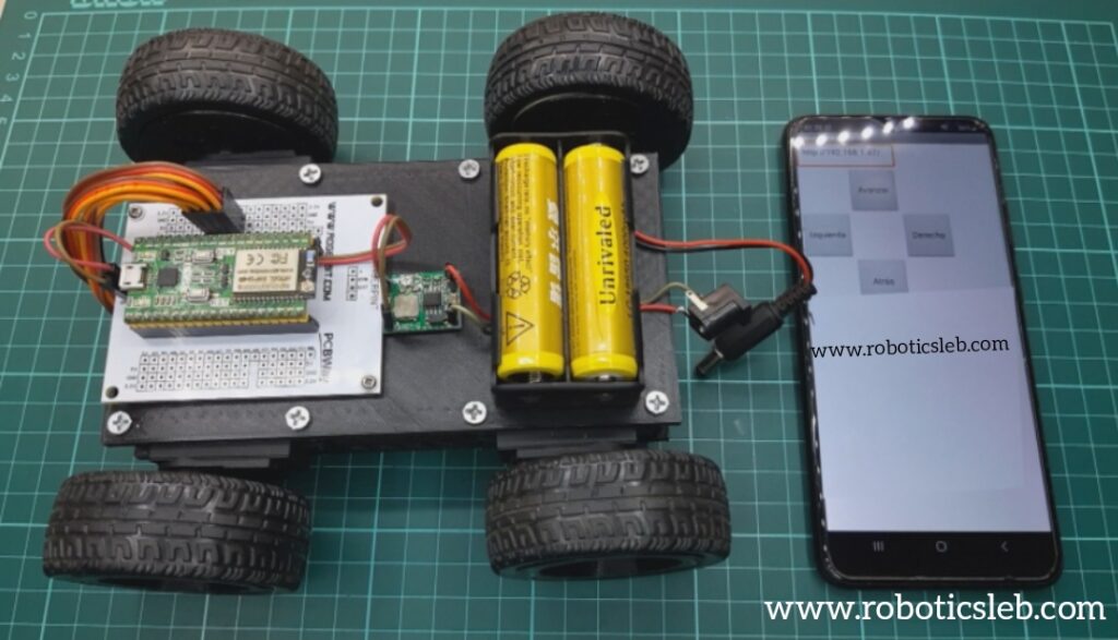
8. Access the ESP32 Web Server
Once connected, the Serial Monitor will display the ESP32’s IP address (e.g., 192.168.x.x).
Open a web browser and enter the IP address in the URL bar.
You’ll see a web page with control buttons for “Avanzar” (Forward), “Retroceder” (Backward), “Derecha” (Right), “Izquierda” (Left), and “Parar” (Stop).
9.Control the Servo Motors
Click the buttons on the web page to send commands to the ESP32, which will control the connected servo motors as per the button pressed.
10. Test and Debug
Ensure all servo motors are correctly connected to the pins specified in your code (12, 14, 27, and 26).
Test the response of the motors based on the commands sent from the web interface.


