Complete Guide to Building a RFID Door Lock System with Arduino
In today’s fast-evolving technological world, ensuring the safety and security of our homes, offices, and valuable possessions is a top priority. Traditional door lock systems, while reliable, often fall short when it comes to providing the level of security and convenience demanded by modern lifestyles. This is where smart door lock systems come into play, blending innovation and technology to create a robust solution.
In this project, we will dive into creating aRFID Door Lock System using Arduino, an RFID Reader, a PIR Motion Sensor, and a Servo Motor. This intelligent system will integrate two essential functionalities:
- RFID Card Authentication – It will allow only authorized users to unlock the door by reading and verifying RFID cards or tags.
- Motion Detection – It will detect motion using a PIR sensor, triggering the door to open automatically for additional convenience.
This system not only enhances security but also introduces automation and ease of use, making it a perfect addition to modern homes and offices.
Project Overview: A Detailed Explanation
The smart door lock system we are building is designed with two key objectives: security and automation. Let’s explore these objectives in greater detail.
Security through RFID Authentication
The use of RFID (Radio Frequency Identification) technology ensures that only individuals possessing authorized RFID cards or tags can unlock the door. RFID readers work by scanning the unique ID embedded in the card or tag and matching it with pre-stored data. If a match is found, the door is unlocked; otherwise, access is denied. This makes the system highly secure and eliminates the risk of unauthorized entry.
Automation with Motion Detection
A PIR (Passive Infrared) motion sensor is integrated into the system to enhance automation. The PIR sensor detects motion within its range and automatically triggers the servo motor to open the door. This feature is especially useful when the user’s hands are occupied, providing a hands-free entry experience.
Modern and Efficient Security Solution
By combining RFID authentication and motion detection, this project offers a highly effective and user-friendly solution. It is ideal for residential spaces, offices, and even areas requiring restricted access, such as laboratories or server rooms. The seamless operation of the system ensures convenience without compromising on safety.
Key Highlights of the Smart Door Lock System
- Enhanced Security: Ensures that only authorized users can unlock the door, providing peace of mind to homeowners and office administrators.
- Automation for Convenience: Automatically detects motion and opens the door, adding a layer of sophistication and ease of use.
- Customizable and Expandable: The system can be further expanded to include additional features, such as remote control via a smartphone app, biometric authentication, or integration with other smart home devices.
This comprehensive project not only demonstrates the capabilities of Arduino but also provides an opportunity to explore cutting-edge technologies like RFID and PIR sensors. Whether you’re a hobbyist, a student, or a professional, this project serves as an excellent example of how technology can be leveraged to enhance everyday security systems.
Required Components
To build this project, you will need the following components:
- Arduino Uno: The microcontroller board that will act as the brain of the system.
- RFID Module (RC522): Used to read RFID cards or tags for authentication.
- PIR Motion Sensor: Detects motion and triggers the door-opening process.
- Servo Motor: Controls the physical opening and closing of the door.
- LEDs (Red and Green): Indicators for authorized (green) or unauthorized (red) access attempts.
- Buzzer: Sounds an alert for unauthorized access.
- Resistors (220Ω): For proper functioning of LEDs.
- Breadboard and Jumper Wires: For easy connections between components.
Circuit Diagram and Connections
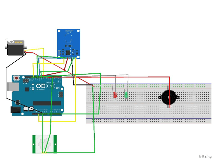
RFID Module Connections:
- SDA → Pin 10
- SCK → Pin 13
- MOSI → Pin 11
- MISO → Pin 12
- RST → Pin 9
- VCC → 3.3V
- GND → GND
PIR Motion Sensor Connections:
- Signal → Pin 4
- VCC → 5V
- GND → GND
Servo Motor Connections:
- Signal → Pin 8
- VCC → 5V
- GND → GND
LEDs Connections:
- Red LED → Pin 2
- Green LED → Pin 3
Buzzer Connections:
- Signal → Pin 7
Note: Use a proper circuit diagram for error-free connections.
Full Code
#include <RFID.h>
#include <SPI.h>
#include <Servo.h>

#define SS_PIN 10
#define RST_PIN 9
#define SERVO_PIN 8
#define red 2
#define green 3
#define buzzer 7
#define pir 4

int data;

Servo servo;
RFID rfid(SS_PIN, RST_PIN);

boolean card = false;
int rfid_id[5] = {227, 88, 145, 52, 30};
boolean lock = false;

void lock_door() { /// Closes the door.
  if (lock) {
    servo.write(180);
    Serial.println("Door closed.");
    delay(100);
    servo.write(0);
  }
}

void setup() {
  pinMode(red, OUTPUT);
  pinMode(green, OUTPUT);
  pinMode(buzzer, OUTPUT);
  pinMode(pir, INPUT);
  servo.attach(SERVO_PIN);
  Serial.begin(9600);
  SPI.begin();
  rfid.init();
}

void loop() {
  card = true;
  data = digitalRead(pir);
  Serial.print("Veri: ");
  Serial.println(data);
  servo.write(180);
  if (rfid.isCard()) {
    if (rfid.readCardSerial()) {
      Serial.print("ID: ");
      delay(100);
    }
    for (int i = 0; i < 5; i++) {
      Serial.print(rfid.serNum[i]);
      Serial.print(" ");
      delay(100);
    }
    boolean trueid = true;
    for (int i = 0; i < 5; i++) {
      if (rfid_id[i] != rfid.serNum[i]) {
        trueid = false;
        break;
      }
    }
    if (trueid) {
      Serial.println();
      delay(1000);
      Serial.println("Welcome to your room");
      delay(1000);
      digitalWrite(green, HIGH);
      delay(200);
      digitalWrite(red, LOW);
      tone(buzzer, 3);
      delay(1000);
      noTone(buzzer);
      delay(100);
      servo.write(0);
      delay(2000);
      Serial.println("Door opened.");
      delay(1000);
      digitalWrite(green, LOW);
      delay(10000);
      lock_door();
      delay(2000);
      servo.write(180);
      Serial.println("Door closed.");
      while (true) { // Loop to check PIR sensor continuously
        data = digitalRead(pir);
        if (data == 1) {
          Serial.println("Motion detected, opening door.");
          servo.write(0);
          delay(2000); // Door stays open for 2 seconds
          Serial.println("Door opened.");
          tone(buzzer, 3);
          delay(1000);
          noTone(buzzer);
          delay(10000); // Wait for 10 seconds
          servo.write(180);
          Serial.println("Door closed.");
          tone(buzzer, 3);
          delay(2000); // Allow time for door to close
          noTone(buzzer);
        }
        delay(500); // Check every 0.5 seconds
      }
    } else {
      digitalWrite(red, HIGH);
      tone(buzzer, 3);
      delay(1000);
      noTone(buzzer);
      Serial.println("Wrong ID.");
      delay(2000);
      digitalWrite(red, LOW);
    }
  }
}
Library Installation
Before running the code, ensure you install the following libraries in the Arduino IDE:
- RFID.h
- Navigate to Sketch > Include Library > Manage Libraries, search for
RFID, and install it.
- Navigate to Sketch > Include Library > Manage Libraries, search for
- Servo.h
- This library is pre-installed in Arduino IDE.
Code Explanation
Below is an overview of how the Arduino code works:
1. Initialization
pinMode(red, OUTPUT);
pinMode(green, OUTPUT);
pinMode(buzzer, OUTPUT);
pinMode(pir, INPUT);
servo.attach(SERVO_PIN);
Serial.begin(9600);
SPI.begin();
rfid.init();
This section sets up pin modes, attaches the servo motor, and initializes the RFID module.
2. RFID Authentication
The system reads the RFID card or tag’s serial number to verify if it matches the authorized ID.
if (rfid.isCard()) {
  if (rfid.readCardSerial()) {
    for (int i = 0; i < 5; i++) {
      if (rfid_id[i] != rfid.serNum[i]) {
        trueid = false;
        break;
      }
    }
  }
}
3. Servo Motor Control
The servo motor rotates to open and close the door.
servo.write(0); // Open the door
delay(2000);    // Keep the door open for 2 seconds
servo.write(180); // Close the door
4. Motion Detection
When motion is detected by the PIR sensor, the door opens automatically.
if (digitalRead(pir) == 1) {
  servo.write(0); // Open the door
  delay(2000);
  servo.write(180); // Close the door
}
How the System Works
- RFID Authentication
- The RFID reader scans the card or tag. If the ID matches, the green LED lights up, and the door opens. Otherwise, the red LED lights up, and the buzzer sounds an alert.
- Motion Detection
- The PIR sensor detects motion and triggers the servo motor to open the door.
- Automatic Closing
- The door automatically closes after a preset duration for convenience.
Benefits
- Enhanced Security: Ensures only authorized users can access the door.
- Automation: Automatically opens and closes the door when necessary.
- Ease of Use: Simple design with Arduino makes it accessible even for beginners.
Real-Life Applications
- Home or Office Security: Protect homes or workplaces with enhanced security.
- Restricted Access Areas: Ideal for securing restricted zones.
- Smart Homes: A valuable addition to any smart home setup.
Conclusion
The smart door lock system using Arduino is a cost-effective and efficient security solution. With its combination of RFID and PIR sensors, it ensures the safety of both residential and professional spaces. It is simple to build, making it an ideal project for DIY enthusiasts and learners.


