This project detects motion using a PIR sensor and displays the status on a 16×2 LCD display.
Required Components
- Arduino Uno x1
- PIR Motion Sensor (HC-SR501) x1
- 16×2 LCD Display x1
- 10k Ohm Potentiometer x1
- Breadboard x1
- Jumper Wires
- USB Cable for Arduino
Why Do We Need This Project?
This project is essential for creating a simple yet effective motion detection system that can be used in various applications, such as:
- Home Security: Detect unauthorized movement and alert homeowners.
- Automation: Automatically trigger devices like lights or alarms when motion is detected.
- Energy Efficiency: Activate appliances only when someone is present, reducing power consumption.
- Learning Purpose: It’s an excellent project for beginners to understand motion sensors, LCD interfacing, and Arduino programming.
By integrating a PIR motion sensor with an LCD display, this project provides real-time feedback, making it highly practical and educational.
How It Works
- The PIR sensor detects motion by sensing infrared radiation changes in its surroundings. If it detects motion, its OUT pin sends a HIGH signal to the Arduino.
- The Arduino processes this input and controls the LCD display to show the status:
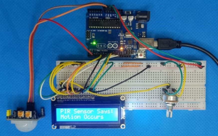
- If motion is detected, the LCD displays “Motion Occurs”.
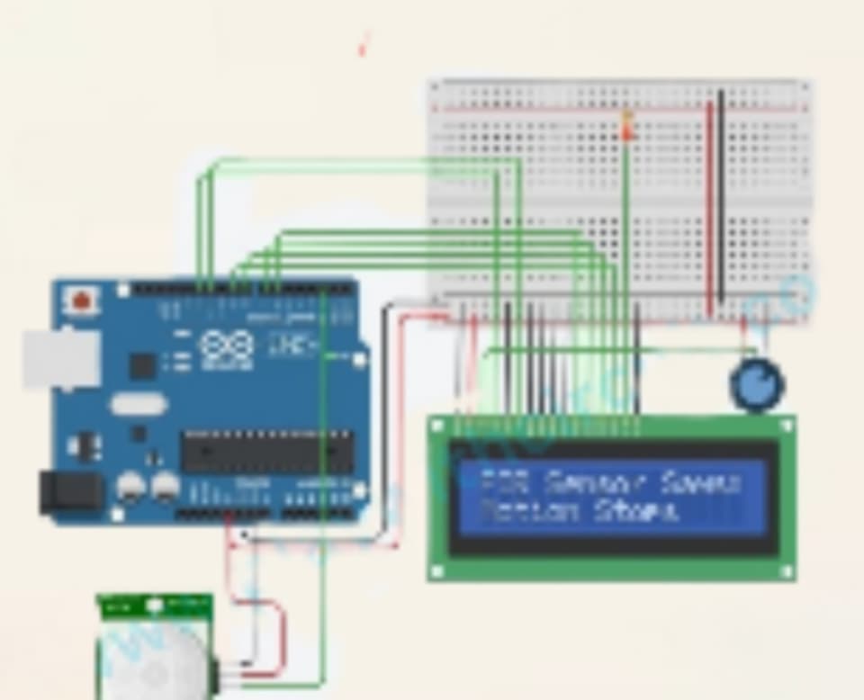
- If no motion is detected, the LCD displays “Motion Stops”.
Steps to Build the Project
- Assemble the components on the breadboard as per the circuit diagram.
- Connect the Arduino to your computer using a USB cable.
- Upload the provided code to the Arduino using the Arduino IDE.
- Adjust the LCD’s contrast using the potentiometer.
- Power the Arduino and test the system.
Circuit Diagram
Code
#include <LiquidCrystal.h> // Include the LiquidCrystal library for LCD display
LiquidCrystal lcd(12, 11, 6, 7, 8, 9); // Initialize the LCD object with pin numbers

int sensorInput = 2;   // PIR sensor input pin
int sensorReturn = 0;  // Variable to store PIR sensor output

void setup() {
  pinMode(sensorInput, INPUT); // Set sensor pin as input
  // Set up the LCD's number of columns and rows
  lcd.begin(16, 2);
  // Print initial message on the LCD
  lcd.setCursor(0, 0);
  lcd.print("PIR Sensor Says:");
  lcd.setCursor(0, 1);
}

void loop() {
  sensorReturn = digitalRead(sensorInput); // Read input value from PIR sensor

  // Check if motion is detected
  if (sensorReturn == HIGH) {
    // Set cursor to the second row and print motion detection message
    lcd.setCursor(0, 1);
    lcd.print("Motion Occurs   ");
  } else {
    // Set cursor to the second row and print motion stopped message
    lcd.setCursor(0, 1);
    lcd.print("Motion Stops    ");
  }
}
Code Explanation
- Library Initialization:
TheLiquidCrystallibrary is included to interface with the LCD.
#include <LiquidCrystal.h>
LiquidCrystal lcd(12, 11, 6, 7, 8, 9);
The lcd object is initialized with the pin numbers connected to the RS, E, D4, D5, D6, and D7 pins of the LCD.
Global Variables:
sensorInputis assigned to pin 2, which receives the output from the PIR sensor.sensorReturnstores the sensor’s status.
Setup:
- The sensorInput pin is set as an INPUT.
- The LCD is initialized with 16 columns and 2 rows using
lcd.begin(16, 2). - An initial message, “PIR Sensor Says:”, is printed on the LCD.
lcd.setCursor(0, 0);
lcd.print("PIR Sensor Says:");
4. Main Loop:
- The PIR sensor’s status is read using
digitalRead(sensorInput). - If the sensor’s output is HIGH, the LCD displays “Motion Occurs”.
- Otherwise, the LCD displays “Motion Stops”.
if (sensorReturn == HIGH) {
    lcd.setCursor(0, 1);
    lcd.print("Motion Occurs   ");
} else {
    lcd.setCursor(0, 1);
    lcd.print("Motion Stops    ");
}
- Display Formatting:
lcd.setCursor(0, 1)sets the cursor position to the second row.- Messages are padded with spaces to overwrite any previous characters on the LCD.
Expected Output
- When no motion is detected, the LCD will show:yamlCopy code
PIR Sensor Says:
Motion Stops
When motion is detected, the LCD will show
PIR Sensor Says:
Motion Occurs
This project is a simple and effective way to monitor motion, and it can be integrated into larger security systems.
Additional Details About the Project
- PIR Sensor Sensitivity:
The PIR sensor’s sensitivity can be adjusted using the onboard potentiometer. This allows you to fine-tune the range for motion detection, making it suitable for different environments. - Power Requirements:
The entire system can be powered via the Arduino’s USB connection or an external power supply. Ensure a stable 5V power source for accurate sensor readings. - Applications:
- Security Systems: This setup can be integrated into alarm systems to detect intruders.
- Automatic Lighting: Use it to turn lights on/off based on motion.
- Industrial Use: Monitor machinery or restricted areas for unauthorized access.
- Improvement Ideas:
- Add a buzzer for an audible alert when motion is detected.
- Connect the Arduino to a Wi-Fi module (e.g., ESP8266) to send motion alerts to a smartphone.
- Use a battery pack for portability.
- Educational Value:
This project is a great learning tool for:- Understanding how PIR sensors work.
- Interfacing an LCD with an Arduino.
- Learning basic electronics and programming concepts.
- Troubleshooting Tips:
- Sensor Not Detecting Motion: Ensure proper connections and adjust the PIR sensor’s sensitivity.
- LCD Display Issues: Check the contrast using the potentiometer and verify pin connections.
- Incorrect Readings: Ensure the PIR sensor is not placed near heat sources or moving objects that can interfere with its detection.
This project not only demonstrates the basic use of sensors and displays but also opens the door to advanced automation and IoT concepts.


