Building a Line-Following Robot with Arduino
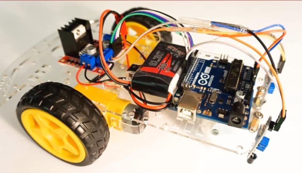
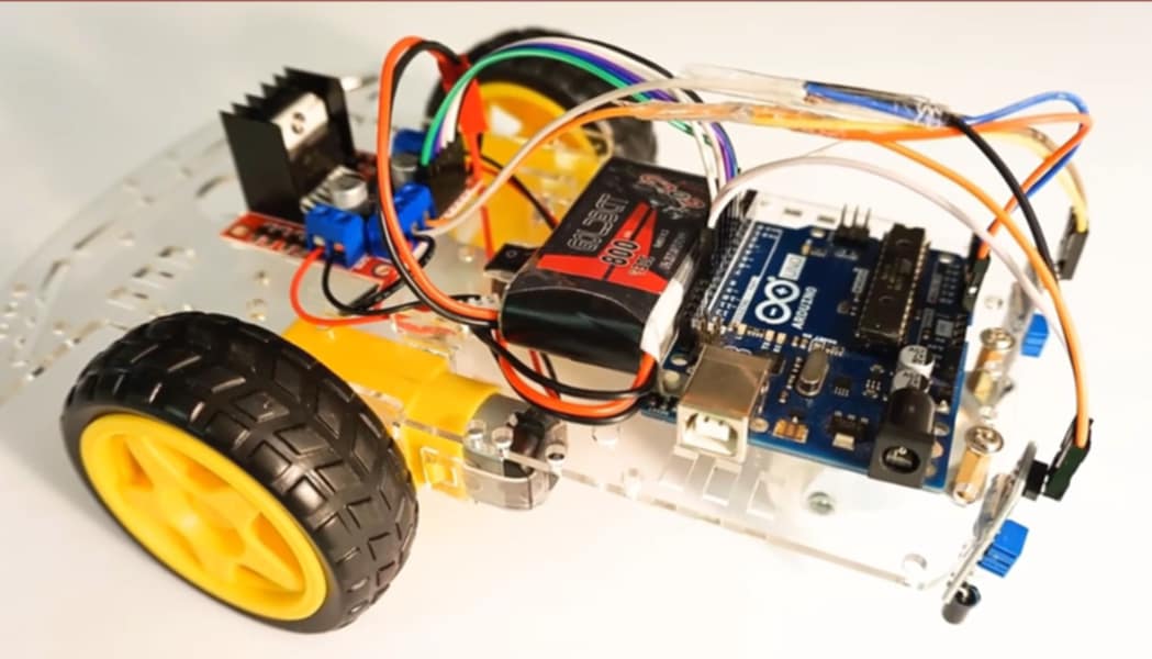
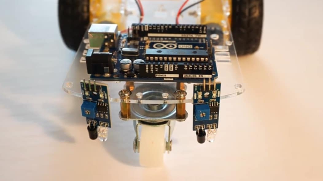
In this project, we will create a line-following robot using Arduino, which will follow a black line. This robot can distinguish between black and white surfaces using infrared (IR) sensors and drive the motors accordingly.
Required Components:
- Arduino Uno
- 2 DC Motors
- L298N Motor Driver Module
- 2 IR Sensors
- Power Supply (Battery)
- Connecting Wires
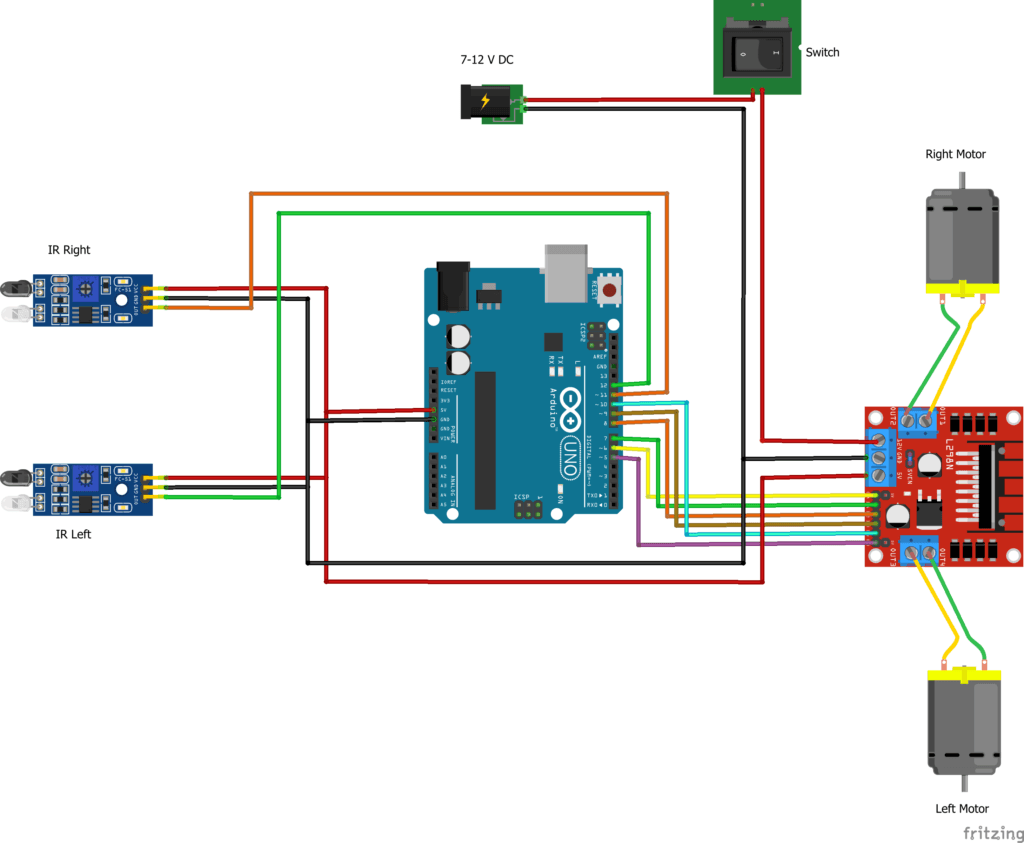
Step 1: Connecting Components
1. Connecting IR Sensors to Arduino
Connect IR sensors to Arduino to detect the black line. The IR sensors emit infrared light and detect reflection to differentiate between black and white surfaces.
- Right IR Sensor:
- VCC: 5V
- GND: GND
- Output: D11 (Arduino digital pin 11)
- Left IR Sensor:
- VCC: 5V
- GND: GND
- Output: D12 (Arduino digital pin 12)
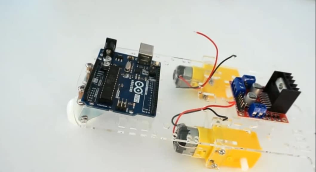
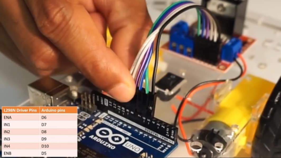
2. Connecting DC Motors to Arduino
Each motor has an enable pin and two directional pins to control the motor speed and direction.
- Right Motor:
- Enable Pin: D6 (PWM)
- Direction Pins: D7 and D8
- Left Motor:
- Enable Pin: D5 (PWM)
- Direction Pins: D9 and D10
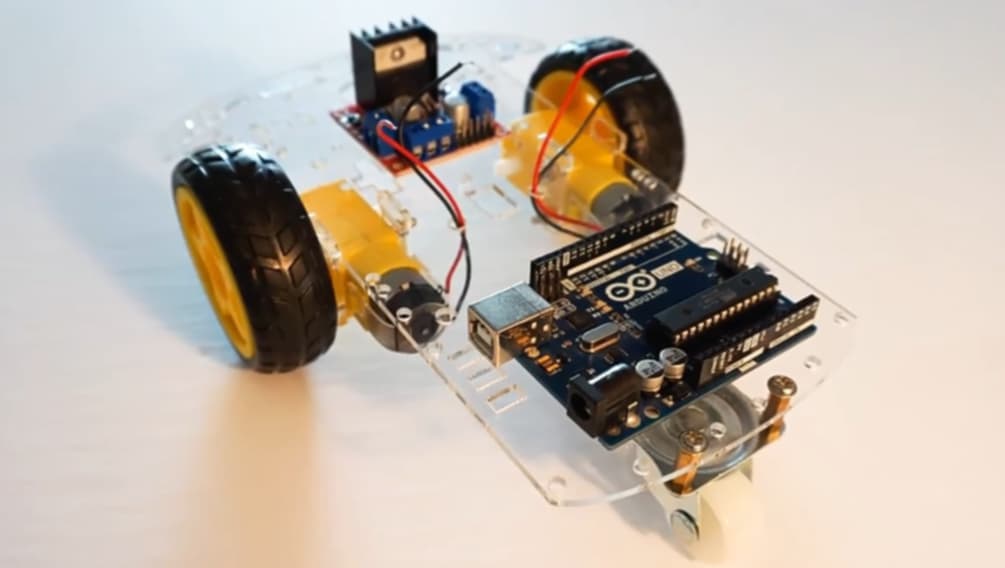
3. Connecting Motor Driver Module
The L298N motor driver module is used to drive the motors. With this module, we can control the speed and direction of the motors.
- Power Connection: Connect the motor driver’s power (VCC) and ground (GND) and link it to Arduino’s GND.
- Arduino to IN1, IN2, IN3, and IN4:
- IN1 -> D7
- IN2 -> D8
- IN3 -> D9
- IN4 -> D10
Step 2: Code Explanation
The code takes signals from the sensors and controls the motor speed and direction. The code is divided into three parts:
- Setup: Sets all pins as input or output and keeps the motors off initially.
- Main Loop: Reads sensor values and adjusts motor speed based on different scenarios.
- rotateMotor Function: Determines motor speed and direction.
Cod. Example: Setup and Main Loop
#define IR_SENSOR_RIGHT 11
#define IR_SENSOR_LEFT 12
#define MOTOR_SPEED 180

void setup() {
  // Set PWM frequency
  TCCR0B = TCCR0B & B11111000 | B00000010;

  // Set up motor pins
  pinMode(6, OUTPUT); // Right motor enable
  pinMode(7, OUTPUT);
  pinMode(8, OUTPUT);

  pinMode(5, OUTPUT); // Left motor enable
  pinMode(9, OUTPUT);
  pinMode(10, OUTPUT);

  // Set up IR sensor pins
  pinMode(IR_SENSOR_RIGHT, INPUT);
  pinMode(IR_SENSOR_LEFT, INPUT);

  // Start with motors off
  rotateMotor(0, 0);
}

void loop() {
  int rightIRSensorValue = digitalRead(IR_SENSOR_RIGHT);
  int leftIRSensorValue = digitalRead(IR_SENSOR_LEFT);

  if (rightIRSensorValue == LOW && leftIRSensorValue == LOW) {
    rotateMotor(MOTOR_SPEED, MOTOR_SPEED); // Move forward
  } else if (rightIRSensorValue == HIGH && leftIRSensorValue == LOW) {
    rotateMotor(-MOTOR_SPEED, MOTOR_SPEED); // Turn right
  } else if (rightIRSensorValue == LOW && leftIRSensorValue == HIGH) {
    rotateMotor(MOTOR_SPEED, -MOTOR_SPEED); // Turn left
  } else {
    rotateMotor(0, 0); // Stop
  }
}
Motor Control: rotateMotor() Function
This function sets motor speed and direction. Positive speed moves the motor forward, negative speed moves it backward, and zero speed stops it.
void rotateMotor(int rightMotorSpeed, int leftMotorSpeed) {
  if (rightMotorSpeed < 0) {
    digitalWrite(7, LOW);
    digitalWrite(8, HIGH);
  } else if (rightMotorSpeed > 0) {
    digitalWrite(7, HIGH);
    digitalWrite(8, LOW);
  } else {
    digitalWrite(7, LOW);
    digitalWrite(8, LOW);
  }

  if (leftMotorSpeed < 0) {
    digitalWrite(9, LOW);
    digitalWrite(10, HIGH);
  } else if (leftMotorSpeed > 0) {
    digitalWrite(9, HIGH);
    digitalWrite(10, LOW);
  } else {
    digitalWrite(9, LOW);
    digitalWrite(10, LOW);
  }

  analogWrite(6, abs(rightMotorSpeed));
  analogWrite(5, abs(leftMotorSpeed));
}
Step 3: Testing the Robot
- Run the Robot: Place the robot on a white surface with a black line and turn it on.
- Adjust Speed: Adjust the speed by changing the
MOTOR_SPEEDvalue. - Sensor Adjustment: Position the sensors properly to detect the black line accurately.
Success Tips:
- Surface and Line: Ensure there is a clear contrast between the black line and white surface.
- Power Supply: Use a reliable power source.
- Future Improvements: Consider adding PID control for smoother performance.


Daigram
Complete COD
#define IR_SENSOR_RIGHT 11
#define IR_SENSOR_LEFT 12
#define MOTOR_SPEED 180

//Right motor
int enableRightMotor=6;
int rightMotorPin1=7;
int rightMotorPin2=8;

//Left motor
int enableLeftMotor=5;
int leftMotorPin1=9;
int leftMotorPin2=10;

void setup()
{

  TCCR0B = TCCR0B & B11111000 | B00000010 ;

  // put your setup code here, to run once:
  pinMode(enableRightMotor, OUTPUT);
  pinMode(rightMotorPin1, OUTPUT);
  pinMode(rightMotorPin2, OUTPUT);

  pinMode(enableLeftMotor, OUTPUT);
  pinMode(leftMotorPin1, OUTPUT);
  pinMode(leftMotorPin2, OUTPUT);

  pinMode(IR_SENSOR_RIGHT, INPUT);
  pinMode(IR_SENSOR_LEFT, INPUT);
  rotateMotor(0,0);
}


void loop()
{

  int rightIRSensorValue = digitalRead(IR_SENSOR_RIGHT);
  int leftIRSensorValue = digitalRead(IR_SENSOR_LEFT);

  //If none of the sensors detects black line, then go straight
  if (rightIRSensorValue == LOW && leftIRSensorValue == LOW)
  {
    rotateMotor(MOTOR_SPEED, MOTOR_SPEED);
  }
  //If right sensor detects black line, then turn right
  else if (rightIRSensorValue == HIGH && leftIRSensorValue == LOW )
  {
      rotateMotor(-MOTOR_SPEED, MOTOR_SPEED);
  }
  //If left sensor detects black line, then turn left
  else if (rightIRSensorValue == LOW && leftIRSensorValue == HIGH )
  {
      rotateMotor(MOTOR_SPEED, -MOTOR_SPEED);
  }
  //If both the sensors detect black line, then stop
  else
  {
    rotateMotor(0, 0);
  }
}


void rotateMotor(int rightMotorSpeed, int leftMotorSpeed)
{

  if (rightMotorSpeed < 0)
  {
    digitalWrite(rightMotorPin1,LOW);
    digitalWrite(rightMotorPin2,HIGH);
  }
  else if (rightMotorSpeed > 0)
  {
    digitalWrite(rightMotorPin1,HIGH);
    digitalWrite(rightMotorPin2,LOW);
  }
  else
  {
    digitalWrite(rightMotorPin1,LOW);
    digitalWrite(rightMotorPin2,LOW);
  }

  if (leftMotorSpeed < 0)
  {
    digitalWrite(leftMotorPin1,LOW);
    digitalWrite(leftMotorPin2,HIGH);
  }
  else if (leftMotorSpeed > 0)
  {
    digitalWrite(leftMotorPin1,HIGH);
    digitalWrite(leftMotorPin2,LOW);
  }
  else
  {
    digitalWrite(leftMotorPin1,LOW);
    digitalWrite(leftMotorPin2,LOW);
  }
  analogWrite(enableRightMotor, abs(rightMotorSpeed));
  analogWrite(enableLeftMotor, abs(leftMotorSpeed));
}


Hola buenas noches, una consulta, de cuanto voltaje es la batería que alimenta el arduino y el L298N. Gracias.
Hello, a question, how much voltage is the battery that powers the Arduino and the L298N. Thank you.
5 VOLT – 7 Volt
Thanks
Pls where should we put the Aurdino code at ?