Wifi Jammer Using Arduino and nRF24L01
Introduction
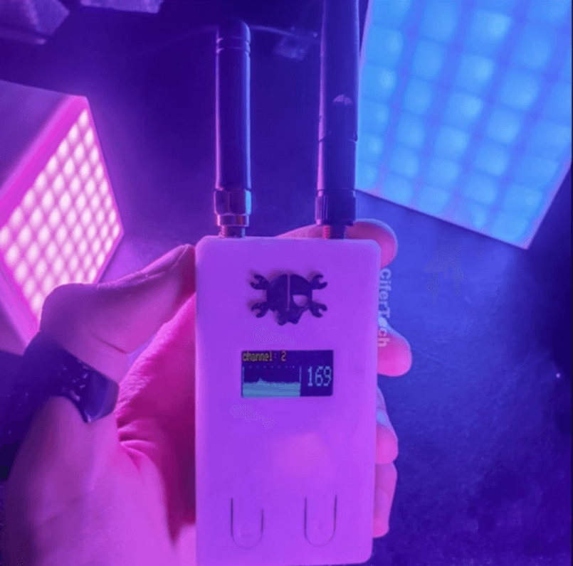
In this project, we will develop a WiFi Jammer using an Arduino Nano, an nRF24L01 transceiver module, and an SSD1306 OLED display. The system will scan and detect 2.4GHz signals from nearby WiFi networks, visualize the detected signals, and display the data on the OLED screen in real-time. This project provides insights into wireless communication, network detection, and signal analysis.
How the WiFi Jammer Works
- The nRF24L01 transceiver module operates within the 2.4GHz frequency band, which is commonly used by WiFi, Bluetooth, and other wireless communication devices.
- It scans the environment for active WiFi signals and captures data related to their signal strength and activity.
- The Arduino Nano acts as the processing unit, analyzing the received data and sending it to the SSD1306 OLED display for visualization.
- The OLED screen presents a graphical representation of nearby WiFi signals, helping to identify network congestion and activity in the area.
Features of the Project
✔️ Real-Time Signal Detection – Continuously scans and detects 2.4GHz WiFi signals.
✔️ Live Data Visualization – Displays network activity on the OLED screen in a graphical format.
✔️ Portable and Compact – Built using small and low-power components.
✔️ WiFi Network Monitoring – Helps in identifying active WiFi channels and signal interference.
Required Components
| Component | Quantity |
|---|---|
| Arduino Nano | 1 |
| nRF24L01 Module | 1 |
| SSD1306 OLED Display | 1 |
| Jumper Wires | As Needed |
| Breadboard | 1 |
| Push Buttons | 2 |
Circuit Connections
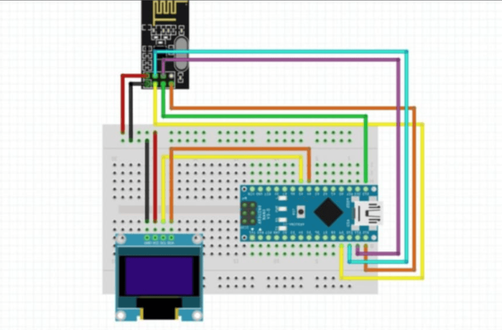
1. nRF24L01 Connections
| nRF24L01 Pin | Arduino Pin |
|---|---|
| VCC | 3.3V |
| GND | GND |
| CE | D7 |
| CSN | D8 |
| SCK | D13 |
| MOSI | D11 |
| MISO | D12 |
2. SSD1306 OLED Connections
| OLED Pin | Arduino Pin |
|---|---|
| GND | GND |
| VCC | 5V |
| SCL | A5 |
| SDA | A4 |
3. Push Button Connections
| Button | Arduino Pin |
|---|---|
| Button 1 | D2 |
| Button 2 | D3 |
Code Explanation
- Library Import
SPI.handWire.hare used for nRF24L01 and OLED display communication.Adafruit_SSD1306.handAdafruit_GFX.hhandle the OLED display.RF24.his required for the nRF24L01 transceiver module.
- Channel Scanning
- The
scanChannels()function scans 2.4GHz channels and stores the results in an array.
- The
- Data Display on OLED
- The
outputChannels()function displays the scanned data in a graphical form on the OLED display.
- The
- Push Button Functionality
pressBt01()switches between channels.pressBt02()toggles the jamming mode.
- Jamming Mode
- The
jammer()function sends a network-jamming signal to a specified channel.
- The
Arduino Code
#include <SPI.h>
#include <Wire.h>
#include <Adafruit_GFX.h>
#include <Adafruit_SSD1306.h>
#define OLED_RESET 4

#include <RF24.h>
#include <nRF24L01.h>
#include "printf.h"

#define CE  7
RF24 radio(7, 8);

#define CHANNELS  64
int channel[CHANNELS];

int  line;
char grey[] = " .:-=+*aRW";

#define _NRF24_CONFIG      0x00
#define _NRF24_EN_AA       0x01
#define _NRF24_RF_CH       0x05
#define _NRF24_RF_SETUP    0x06
#define _NRF24_RPD         0x09

#define BT1 2
#define BT2 3

Adafruit_SSD1306 display = Adafruit_SSD1306(128, 32, &Wire);

byte count;
byte sensorArray[128];
byte drawHeight;

char filled = 'F';
char drawDirection = 'R';
char slope = 'W';

const uint8_t num_channels = 64;
int values[num_channels];
int valuesDisplay[32];
int channels = 0;
const byte address[6] = "00001";
const int num_reps = 50;
bool jamming = true;

byte getRegister(byte r)
{
 byte c;

 PORTB &=~_BV(2);
 c = SPI.transfer(r&0x1F);
 c = SPI.transfer(0);
 PORTB |= _BV(2);

 return(c);
}


void setup()
{
 Serial.begin(57600);

 display.begin(SSD1306_SWITCHCAPVCC, 0x3C);
 display.clearDisplay();

  radio.begin();
  radio.startListening();
  radio.stopListening();

  pinMode(BT1, INPUT_PULLUP);
  pinMode(BT2, INPUT_PULLUP);

  attachInterrupt(digitalPinToInterrupt(BT1), pressBt01, FALLING);
  attachInterrupt(digitalPinToInterrupt(BT2), pressBt02, FALLING);

 for (count = 0; count <= 128; count++)
  {
    sensorArray[count] = 0;
  }

 Serial.println("Starting 2.4GHz Scanner ...");
 Serial.println();


 Serial.println("Channel Layout");
 printChannels();

 SPI.begin();
 SPI.setDataMode(SPI_MODE0);
 SPI.setClockDivider(SPI_CLOCK_DIV2);
 SPI.setBitOrder(MSBFIRST);

 pinMode(CE,OUTPUT);
 disable();

 powerUp();

 setRegister(_NRF24_EN_AA,0x0);


 setRegister(_NRF24_RF_SETUP,0x0F);

}

void setRegister(byte r, byte v)
{
 PORTB &=~_BV(2);
 SPI.transfer((r&0x1F)|0x20);
 SPI.transfer(v);
 PORTB |= _BV(2);
}

void powerUp(void)
{
 setRegister(_NRF24_CONFIG,getRegister(_NRF24_CONFIG)|0x02);
 delayMicroseconds(130);
}

void powerDown(void)
{
 setRegister(_NRF24_CONFIG,getRegister(_NRF24_CONFIG)&~0x02);
}

void enable(void)
{
   PORTB |= _BV(1);
}

void disable(void)
{
   PORTB &=~_BV(1);
}

void setRX(void)
{
 setRegister(_NRF24_CONFIG,getRegister(_NRF24_CONFIG)|0x01);
 enable();

 delayMicroseconds(100);
}

void scanChannels(void)
{
 disable();
 for( int j=0 ; j<255  ; j++)
 {
   for( int i=0 ; i< channels; i++)
   {
     setRegister(_NRF24_RF_CH,(128*i)/ channels);

     setRX();

     delayMicroseconds(40);

     disable();

     if( getRegister(_NRF24_RPD)>0 )   channel[i]++;
   }
 }
}

void outputChannels(void)
{
 int norm = 0;

 for( int i=0 ; i<CHANNELS ; i++)
   if( channel[i]>norm ) norm = channel[i];

 Serial.print('|');
 for( int i=0 ; i<CHANNELS ; i++)
 {
   int pos;

   if( norm!=0 ) pos = (channel[i]*10)/norm;
   else          pos = 0;

   if( pos==0 && channel[i]>0 ) pos++;

   if( pos>9 ) pos = 9;

   Serial.print(grey[pos]);
   channel[i] = 0;
 }

 Serial.print("| ");
 Serial.println(norm);


  display.setCursor(90, 10);
  display.setTextSize(2);
  display.setTextColor(WHITE);
  display.print(norm);
  display.setCursor(90, 8);
  display.setTextSize(1);
  display.setTextColor(WHITE);
  display.print("");


  display.drawLine(0, 10, 0, 32, WHITE);
  display.drawLine(80, 10, 80, 32, WHITE);


  for (count = 10; count < 80; count += 10)
  {
    display.drawPixel(count, 10 , WHITE);
    display.drawPixel(count, 31 , WHITE);
  }


  drawHeight = map(norm, 0, 500, 0, 32 );
  sensorArray[0] = drawHeight;

  for (count = 1; count <= 80; count++ )
  {
    if (filled == 'D' || filled == 'd')
    {
      if (drawDirection == 'L' || drawDirection == 'l')
      {
        display.drawPixel(count, 32 - sensorArray[count - 1], WHITE);
      }
      else //else, draw dots from right to left
      {
        display.drawPixel(80 - count, 32 - sensorArray[count - 1], WHITE);
      }
    }


    else
    {
      if (drawDirection == 'L' || drawDirection == 'l')
      {
        if (slope == 'W' || slope == 'w')
        {
          display.drawLine(count, 32, count, 32 - sensorArray[count - 1], WHITE);
        }
        else
        {
          display.drawLine(count, 1, count, 32 - sensorArray[count - 1], WHITE);

        }
      }


      else
      {
        if (slope == 'W' || slope == 'w')
        {
          display.drawLine(80 - count, 32, 80 - count, 32 - sensorArray[count - 1], WHITE);
        }
        else
        {
          display.drawLine(80 - count, 1, 80 - count, 32 - sensorArray[count - 1], WHITE);
        }
      }
    }
  }

 // drawAxises();
  display.display();
  display.clearDisplay();

  for (count = 80; count >= 2; count--)
  {
    sensorArray[count - 1] = sensorArray[count - 2];
  }
}

void printChannels(void)
{
 Serial.println(">      1 2  3 4  5  6 7 8  9 10 11 12 13  14                     <");
}


void jammer() {
  const char text[] = "xxxxxxxxxxxxxxxx"; // send the noise
  for (int i = ((channels * 5) + 1); i < ((channels * 5) + 23); i++) {
    radio.setChannel(i);
    radio.write( & text, sizeof(text));
  }
 }

void pressBt01() {
  static unsigned long last_interrupt_time = 0;
  unsigned long interrupt_time = millis();
  if (interrupt_time - last_interrupt_time > 200) {
    if (channels < 13) {
      channels++;
    } else {
      channels = 0;
    }
  }
  last_interrupt_time = interrupt_time;
}

void pressBt02() {
  jamming = !jamming;
  delay(200);
}

void loop()
{
  display.clearDisplay();
  display.setTextSize(1);
  display.setTextColor(WHITE);
  display.setCursor(0, 0);
  display.print("channel: " + String(channels + 1));
  //display.display();

 if (jamming) {
    display.clearDisplay();
    display.setTextSize(1);
    display.setTextColor(WHITE);
    display.setCursor(0, 0);
    display.println(("JAMMING CHANNEL" + String(channels + 1)));

    radio.setPALevel(RF24_PA_HIGH);
    radio.setDataRate(RF24_2MBPS);
    display.display();
  }
  while (jamming) {
    jammer();
  }

 scanChannels();

 outputChannels();

 if( line++>12 )
 {
   printChannels();
   line = 0;
 }
}
Benefits of the Project
- Wireless Network Analysis
- Detect nearby devices operating at 2.4GHz frequency.
- Useful for prototyping wifi network jamming experiments.
How to Use the Wifi Jammer
This section will guide you on how to operate the Wireless Channel Scanner you just built using the Arduino Nano, nRF24L01 module, and SSD1306 OLED display.
Steps to Use
1. Powering the System
- Connect the Arduino Nano to your computer using a USB cable, or power it through an external power supply (5V).
- Make sure all connections are secure and the nRF24L01 module is connected to 3.3V (not 5V).
2. Channel Scanning
- Default Mode: Once powered on, the system starts scanning 2.4GHz channels automatically.
- The OLED display will show:
- A graphical bar for each scanned channel.
- The signal strength represented by the bar’s height.
- The values refresh continuously, allowing you to monitor real-time data.
3. Switching Channels
- Use Button 1 (connected to pin D2) to switch between channels.
- Pressing the button will cycle through channels 1–14.
- The current channel will be displayed on the OLED screen.
4. Jamming Mode
- To activate or deactivate Jamming Mode, press Button 2 (connected to pin D3).
- When Jamming Mode is active:
- The OLED display will show “JAMMING CHANNEL X”, where X is the current channel.
- The system will send interference signals to the selected channel.
- Press Button 2 again to exit jamming mode and return to scanning mode.
5. Understanding the Display
- Graphical Bars: Represent the signal strength for each 2.4GHz channel. Taller bars indicate stronger signals.
- Channel Number: Displayed on the top-left corner of the OLED screen.
- Signal Strength Value: Shown numerically on the top-right corner of the OLED screen.
Practical Applications
- Wireless Network Monitoring
- Use this scanner to identify which 2.4GHz channels have the strongest signals.
- This helps in troubleshooting Wi-Fi or Bluetooth interference issues.
- Identifying Free Channels
- Scan for less crowded channels to optimize your router or wireless devices.
- Prototyping and Testing
- Test the jamming functionality for educational or experimental purposes.
- Real-Time Monitoring
- Continuously monitor the environment to see how wireless signals behave in your area.
Safety Notes
- Jamming Signals: Use the jamming feature responsibly. Network jamming is illegal in many countries, so only use it for educational and experimental purposes in a controlled environment.
- Avoid powering the nRF24L01 with 5V, as it could damage the module.
Final Note
This project is easy to build and highly effective for wireless device analysis. If you have any questions or need help, let us know in the comments section! For more interesting projects, visit our website regularly.
Share this post and stay connected with us on Facebook!


good project
where shall you connect the push buttons
How we can use 2 NRF24l01 modules to increase power of signal?