How to Build a Gesture-Controlled Robot with Arduino and nRF24L01
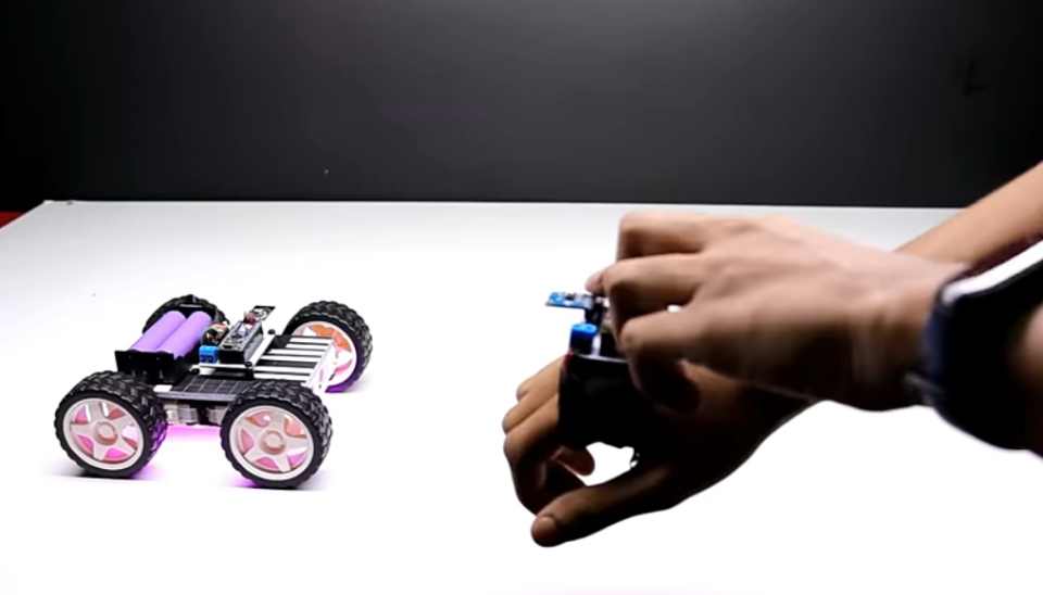
This project focuses on creating a gesture-controlled robot using Arduino and the nRF24L01 transceiver module. By tilting an accelerometer in various directions, the robot will move forward, backward, left, or right accordingly. This tutorial explains each step in detail, from component requirements to the full setup and coding.
Required Components
- Arduino UNO (2 units) – One for the transmitter and one for the receiver.
- nRF24L01 Transceiver Module (2 units) – Enables wireless communication between the transmitter and receiver.
- Motor Driver Module (L298N) – Used to control the motors for movement.
- Accelerometer (e.g., ADXL335 or MPU6050) – To capture hand gestures.
- DC Motors (2 units) – For driving the robot.
- Robot chassis, wheels, and battery pack – To house all components and provide power.
Step 1: Setting Up the Transmitter Circuit
The transmitter circuit includes an accelerometer and the nRF24L01 module. This part of the circuit reads gesture data from the accelerometer and sends it to the receiver.
Circuit Connections for Transmitter
- Connect the X-axis pin of the accelerometer to the A0 pin of the Arduino.
- Connect the Y-axis pin of the accelerometer to the A1 pin of the Arduino.
- nRF24L01 Connections:
- CE to pin 8 on Arduino.
- CSN to pin 10 on Arduino.
- SCK to pin 13 on Arduino.
- MOSI to pin 11 on Arduino.
- MISO to pin 12 on Arduino.
- Power the nRF24L01 module with 3.3V (do not use 5V as it may damage the module).
Transmitter Code
This code reads data from the accelerometer and transmits it via the nRF24L01 module.
#include <SPI.h>
#include <nRF24L01.h>
#include <RF24.h>

const int x_out = A0; // X-axis of accelerometer connected to A0
const int y_out = A1; // Y-axis of accelerometer connected to A1

RF24 radio(8, 10); // CE and CSN pins for nRF24L01
const byte address[6] = "00001"; // Communication address

struct data {
  int xAxis;
  int yAxis;
};
data send_data;

void setup() {
  radio.begin();
  radio.openWritingPipe(address);
  radio.setPALevel(RF24_PA_MIN);
  radio.setDataRate(RF24_250KBPS);
  radio.stopListening();
}

void loop() {
  send_data.xAxis = analogRead(x_out); // Read X-axis
  send_data.yAxis = analogRead(y_out); // Read Y-axis
  radio.write(&send_data, sizeof(data)); // Send data
  delay(10); // Short delay for stability
}
Upload this code to the transmitter Arduino. This setup will read the X and Y axis values from the accelerometer and send them to the receiver through the nRF24L01 module.
Step 2: Setting Up the Receiver Circuit
The receiver circuit also includes an nRF24L01 module and will use the L298N motor driver to control the robot’s motors based on received data.
Circuit Connections for Receiver
- L298N Motor Driver Connections:
- Connect ENA (motor A speed control) to pin 3 on Arduino.
- Connect ENB (motor B speed control) to pin 9 on Arduino.
- Motor A connections:
- Connect IN1 to pin 4 on Arduino.
- Connect IN2 to pin 5 on Arduino.
- Motor B connections:
- Connect IN3 to pin 6 on Arduino.
- Connect IN4 to pin 7 on Arduino.
- nRF24L01 Connections:
- CE to pin 8 on Arduino.
- CSN to pin 10 on Arduino.
- Connect the L298N motor driver’s power input to an external battery source to ensure the motors receive adequate power.
Receiver Code
The code below receives data from the transmitter and controls the robot’s motors based on the accelerometer’s X and Y-axis readings.
#include <SPI.h>
#include <nRF24L01.h>
#include <RF24.h>

int ENA = 3;     // Motor A speed control
int ENB = 9;     // Motor B speed control
int MotorA1 = 4; // Motor A direction pin 1
int MotorA2 = 5; // Motor A direction pin 2
int MotorB1 = 6; // Motor B direction pin 1
int MotorB2 = 7; // Motor B direction pin 2

RF24 radio(8, 10); // CE and CSN pins for nRF24L01
const byte address[6] = "00001"; // Same address as transmitter

struct data {
  int xAxis;
  int yAxis;
};
data receive_data;

void setup() {
  Serial.begin(9600);
  radio.begin();
  radio.openReadingPipe(0, address);
  radio.setPALevel(RF24_PA_MIN);
  radio.setDataRate(RF24_250KBPS);
  radio.startListening();

  pinMode(ENA, OUTPUT);
  pinMode(ENB, OUTPUT);
  pinMode(MotorA1, OUTPUT);
  pinMode(MotorA2, OUTPUT);
  pinMode(MotorB1, OUTPUT);
  pinMode(MotorB2, OUTPUT);
}

void loop() {
  while (radio.available()) {
    radio.read(&receive_data, sizeof(data));

    if (receive_data.yAxis > 400) { // Move Forward
      digitalWrite(MotorA1, LOW);
      digitalWrite(MotorA2, HIGH);
      digitalWrite(MotorB1, HIGH);
      digitalWrite(MotorB2, LOW);
      analogWrite(ENA, 150);
      analogWrite(ENB, 150);
    } else if (receive_data.yAxis < 320) { // Move Backward
      digitalWrite(MotorA1, HIGH);
      digitalWrite(MotorA2, LOW);
      digitalWrite(MotorB1, LOW);
      digitalWrite(MotorB2, HIGH);
      analogWrite(ENA, 150);
      analogWrite(ENB, 150);
    } else if (receive_data.xAxis < 320) { // Turn Left
      digitalWrite(MotorA1, HIGH);
      digitalWrite(MotorA2, LOW);
      digitalWrite(MotorB1, HIGH);
      digitalWrite(MotorB2, LOW);
      analogWrite(ENA, 150);
      analogWrite(ENB, 150);
    } else if (receive_data.xAxis > 400) { // Turn Right
      digitalWrite(MotorA1, LOW);
      digitalWrite(MotorA2, HIGH);
      digitalWrite(MotorB1, LOW);
      digitalWrite(MotorB2, HIGH);
      analogWrite(ENA, 150);
      analogWrite(ENB, 150);
    } else { // Stop
      digitalWrite(MotorA1, LOW);
      digitalWrite(MotorA2, LOW);
      digitalWrite(MotorB1, LOW);
      digitalWrite(MotorB2, LOW);
      analogWrite(ENA, 0);
      analogWrite(ENB, 0);
    }
  }
}
Upload this code to the receiver Arduino. This setup will receive the X and Y-axis values from the transmitter and drive the motors accordingly.
Project Operation
Once the circuit and code are ready, you can control the robot by tilting the accelerometer in different directions. Here’s how it works:
- Forward Movement: Tilt the accelerometer forward (Y-axis value increases), and the robot will move forward.
- Backward Movement: Tilt the accelerometer backward (Y-axis value decreases), and the robot will move backward.
- Left Turn: Tilt the accelerometer to the left (X-axis value decreases), and the robot will turn left.
- Right Turn: Tilt the accelerometer to the right (X-axis value increases), and the robot will turn right.
- Stop: Keep the accelerometer flat, and the robot will stop.
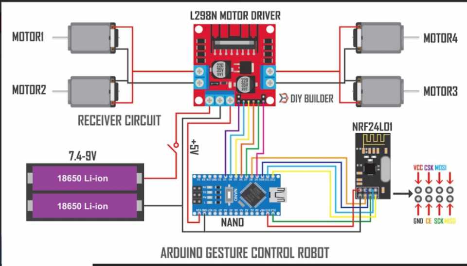
Daigram


1 thought on “Gesture Controlled Robot with Arduino and nRF24L01”