
Building a Gesture -Bluetooth-Controlled Robot Car Using Arduino & MPU6050: Complete Guide
Today, we are going to build an exciting robotics project where an Arduino-based robot car is controlled using the MPU6050 sensor (Accelerometer & Gyroscope) and Bluetooth communication. The MPU6050 sensor will detect hand movements and translate them into motion commands, which will be sent via an HC-05 Bluetooth module to control the robot car’s movement in real time.
Additionally, to make the robot more autonomous, we will integrate an HC-SR04 Ultrasonic Sensor. This sensor will continuously monitor the surroundings and detect obstacles in the path of the robot. If an obstacle is detected, the robot will automatically stop or change direction to avoid collisions, making it a smart and efficient system.
This project is perfect for students, hobbyists, and tech enthusiasts who are eager to explore robotics, microcontrollers, and IoT. It provides hands-on experience in working with motion sensors, wireless communication, and obstacle detection, making it a great learning opportunity for anyone interested in building intelligent robotic systems.
Required Components
To build this robot car, you will need the following components:
| No. | Component | Quantity |
|---|---|---|
| 1 | Arduino Uno | 1 |
| 2 | MPU6050 (Accelerometer & Gyroscope Sensor) | 1 |
| 3 | HC-05 Bluetooth Module | 1 |
| 4 | L298N Motor Driver Module | 1 |
| 5 | DC Motor (Wheel Motor) | 4 |
| 6 | HC-SR04 Ultrasonic Sensor | 1 |
| 7 | 9V Battery / Li-ion Battery Pack | 1 |
| 8 | Jumper Wires & Battery Connectors | As needed |
| 9 | Robot Car Chassis | 1 |
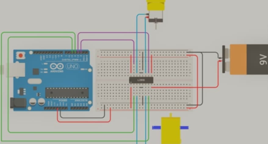
Circuit Connections
1. Connecting MPU6050 (Accelerometer & Gyroscope):
- VCC → 5V (Arduino)
- GND → GND (Arduino)
- SCL → A5 (Arduino)
- SDA → A4 (Arduino)
2. Connecting HC-05 Bluetooth Module:
- VCC → 5V (Arduino)
- GND → GND (Arduino)
- TX → 11 (Arduino)
- RX → 10 (Arduino) [Use a 1KΩ & 2KΩ voltage divider]
3. Connecting L298N Motor Driver:
- IN1 → 3 (Arduino)
- IN2 → 5 (Arduino)
- IN3 → 6 (Arduino)
- IN4 → 9 (Arduino)
- Motor A (Left) → M1 & M2
- Motor B (Right) → M3 & M4
- 12V → Battery positive terminal
- GND → Battery negative terminal
4. Connecting HC-SR04 Ultrasonic Sensor:
- VCC → 5V (Arduino)
- GND → GND (Arduino)
- Trig → 12 (Arduino)
- Echo → 13 (Arduino)
Arduino Code Explanation
1. Reading Data from Gesture MPU6050
#include <Wire.h>

const int MPU=0x68;
float AccX, AccY, AccZ;
float pitch, roll;

void setup(){
  Wire.begin();
  Wire.beginTransmission(MPU);
  Wire.write(0x6B);
  Wire.write(0);
  Wire.endTransmission(true);
  Serial.begin(9600);
}

void loop(){
  Wire.beginTransmission(MPU);
  Wire.write(0x3B);
  Wire.endTransmission(false);
  Wire.requestFrom(MPU, 6, true);

  AccX = (Wire.read() << 8 | Wire.read()) / 16384.0;
  AccY = (Wire.read() << 8 | Wire.read()) / 16384.0;
  AccZ = (Wire.read() << 8 | Wire.read()) / 16384.0;

  pitch = atan(AccY / sqrt(AccX * AccX + AccZ * AccZ)) * 180 / PI;
  roll = atan(-AccX / sqrt(AccY * AccY + AccZ * AccZ)) * 180 / PI;

  Serial.print("Pitch: "); Serial.print(pitch);
  Serial.print(" Roll: "); Serial.println(roll);
  delay(100);
}
This code reads the pitch and roll values from the MPU6050 sensor to detect hand gestures.
2. Receiving Bluetooth Commands and Controlling the Robot
#include <SoftwareSerial.h>

SoftwareSerial BTSerial(10, 11);  // HC-05 connection

void setup() {
  BTSerial.begin(9600);
  pinMode(3, OUTPUT);
  pinMode(5, OUTPUT);
  pinMode(6, OUTPUT);
  pinMode(9, OUTPUT);
}

void loop() {
  if (BTSerial.available()) {
    char command = BTSerial.read();
    if (command == 'F') {  // Move forward
      digitalWrite(3, HIGH);
      digitalWrite(5, LOW);
      digitalWrite(6, HIGH);
      digitalWrite(9, LOW);
    } else if (command == 'B') {  // Move backward
      digitalWrite(3, LOW);
      digitalWrite(5, HIGH);
      digitalWrite(6, LOW);
      digitalWrite(9, HIGH);
    } else if (command == 'L') {  // Turn left
      digitalWrite(3, LOW);
      digitalWrite(5, HIGH);
      digitalWrite(6, HIGH);
      digitalWrite(9, LOW);
    } else if (command == 'R') {  // Turn right
      digitalWrite(3, HIGH);
      digitalWrite(5, LOW);
      digitalWrite(6, LOW);
      digitalWrite(9, HIGH);
    } else {  // Stop
      digitalWrite(3, LOW);
      digitalWrite(5, LOW);
      digitalWrite(6, LOW);
      digitalWrite(9, LOW);
    }
  }
}
This code processes Bluetooth commands and moves the robot accordingly.
3. Obstacle Detection and Avoidance
This code uses an ultrasonic sensor to detect obstacles and stop the robot if needed.
Receiver cod
#include <SoftwareSerial.h>

SoftwareSerial BTSerial(10, 11); //  CONNECT BT RX PIN TO ARDUINO 12 PIN | CONNECT BT TX PIN TO ARDUINO 11 PIN
#include<SPI.h>


int trigPin = 12;    // Trig
int echoPin = 13;    // Echo
long duration,  cm, inches;
int direct;
int l1=3;
int r1=5;
int l2=6;
int r2=9;

int  forword_corr;


int a = 0 ;
int s = 3;


int b = 0 ;
int  c = 2;


void setup() {
  Serial.begin(9600);
  BTSerial.begin(9600);


  pinMode(l1, OUTPUT);
  pinMode(r1,  OUTPUT);
  pinMode(l2, OUTPUT);
  pinMode(r2, OUTPUT);

  digitalWrite(l1,  LOW);
  digitalWrite(r1, LOW);
  digitalWrite(l2, LOW);
  digitalWrite(r2,  LOW);

  pinMode(trigPin, OUTPUT);
  pinMode(echoPin, INPUT);
}

void  loop() {

   digitalWrite(trigPin, LOW);
  delayMicroseconds(5);
  digitalWrite(trigPin, HIGH);
  delayMicroseconds(10);
  digitalWrite(trigPin,  LOW);

  pinMode(echoPin, INPUT);
  duration = pulseIn(echoPin, HIGH);

  cm = (duration/2) / 29.1;     // Divide by 29.1 or multiply by 0.0343
  Serial.print(cm);
  Serial.print("cm");
  Serial.println();
  if(BTSerial.available()>0){  // Witing for data incoming from the other XBee module
   direct=BTSerial.read();

                if(direct == 'B'){
            Serial.println("Backward");
            backward();
          }else if (direct=='F'){
              Serial.println("Forward");
            forward();
          }else if(direct == 'R'){
            Serial.println("Right");
            left();
          }else if(direct == 'L'){
            Serial.println("left");
            right();

           }else if(direct == 'r'){
            Serial.println("rotright");
            rotr();

          }else if(direct == 'l'){
            Serial.println("rotleft");
            rotl();
            }else if  (direct == 'S'){
            Serial.println("Stop");
            stopCar();
          }


  }
}


void forward()
{
  if(cm<=15){
     digitalWrite(l1, LOW);
      digitalWrite(r2, LOW);

    }
    else{
    digitalWrite(l1, HIGH);
  digitalWrite(r1, LOW);
  digitalWrite(l2, LOW);


    digitalWrite(r2, LOW);
 delay(2);
    digitalWrite(r2, HIGH);
   delay(2);
}
}
void backward()
{
  digitalWrite(l1, LOW);
  digitalWrite(l2,  HIGH);
  digitalWrite(r2, LOW);
  if(b%c == 0){
    digitalWrite(r1, HIGH);
  }else{
    digitalWrite(r1, LOW);
   }


    if(b > 1000 ) {
     b=0;
   }
}
void right()
{
  digitalWrite(l1, HIGH);
  digitalWrite(r1,  LOW);
  digitalWrite(l2, LOW);
  analogWrite(r2, 100);


}
void  left()
{
   analogWrite(l1, 100);
  digitalWrite(r1, LOW);
  digitalWrite(l2,  LOW);
  digitalWrite(r2, HIGH);
}

void stopCar() {
    digitalWrite(l1,  LOW);

  digitalWrite(r1, LOW);
  digitalWrite(l2, LOW);
  digitalWrite(r2,  LOW);
}
void rotr() {

  digitalWrite(l1, HIGH);
  digitalWrite(r1,  LOW);
  digitalWrite(l2, HIGH);
  digitalWrite(r2, LOW);
}
void rotl(){

  digitalWrite(l1, LOW);
  digitalWrite(r1, HIGH);
  digitalWrite(l2, LOW);
  digitalWrite(r2, HIGH);
}
#include <Wire.h>
#include <SoftwareSerial.h>
SoftwareSerial BTSerial(10, 11); // CONNECT BT RX PIN TO ARDUINO 11 PIN | CONNECT BT TX PIN TO ARDUINO 10 PIN
const int MPU_ADDRESS = 0x68; // MPU6050 I2C address
float AccX, AccY, AccZ;
float GyroX, GyroY, GyroZ;
float accAngleX, accAngleY, gyroAngleX, gyroAngleY, gyroAngleZ;
float roll, pitch, yaw;
float AccErrorX, AccErrorY, GyroErrorX, GyroErrorY, GyroErrorZ;
float elapsedTime, currentTime, previousTime;
int c = 0;
void setup()
{
Serial.begin(9600);
BTSerial.begin(9600); // HC-05 default speed in AT command more
Wire.begin(); // Initialize comunication
Wire.beginTransmission(MPU_ADDRESS); // Start communication with MPU6050 // MPU=0x68
Wire.write(0x6B); // Talk to the register 6B
Wire.write(0x00); // Make reset - place a 0 into the 6B register
Wire.endTransmission(true); //end the transmission
// Configure Accelerometer Sensitivity - Full Scale Range (default +/- 2g)
/* Wire.beginTransmission(MPU);
Wire.write(0x1C); //Talk to the ACCEL_CONFIG register (1C hex)
Wire.write(0x10); //Set the register bits as 00010000 (+/- 8g full scale range)
Wire.endTransmission(true);
// Configure Gyro Sensitivity - Full Scale Range (default +/- 250deg/s)
Wire.beginTransmission(MPU);
Wire.write(0x1B); // Talk to the GYRO_CONFIG register (1B hex)
Wire.write(0x10); // Set the register bits as 00010000 (1000deg/s full scale)
Wire.endTransmission(true);
delay(20);
//Call this function if you need to get the IMU error values for your module*/
//while(true) calculate_IMU_error();
// delay(20);
}
void loop()
{
MPU_read_accel_data();
MPU_read_gyro_data();
// calculate time elapsed since last time we were here
previousTime = currentTime; // Previous time is stored before the actual time read
currentTime = millis(); // Current time actual time read
elapsedTime = (currentTime - previousTime) / 1000; // Divide by 1000 to get seconds
// Complementary filter - combine acceleromter and gyro angle values
roll = 0.92 * (roll + (GyroX * elapsedTime)) + 0.08 * accAngleX;
pitch = 0.92 * (pitch + (GyroY * elapsedTime)) + 0.08 * accAngleY;
//yaw = gyroAngleZ;
// Currently the raw values are in degrees per seconds, deg/s, so we need to multiply by sendonds (s) to get the angle in degrees
gyroAngleX += GyroX * elapsedTime; // deg/s * s = deg
gyroAngleY += GyroY * elapsedTime;
gyroAngleZ += GyroZ * elapsedTime;
/*by me */
// Print the values on the serial monitor
Serial.print("roll:");
Serial.print(roll);
Serial.print(" ");
Serial.print("pitch:");
Serial.println(pitch);
/* Serial.print(" ");
Serial.print("yaw:");
Serial.println(yaw);*/
/*Serial.print(" ");
/* made by me
// Print the values on the serial monitor
Serial.print(pitch);
Serial.print(" ");
Serial.print(accAngleY);
Serial.print(" ");
Serial.println(gyroAngleY);
*/
if(pitch<-17){
BTSerial.write('F');
}else if(pitch>20){
BTSerial.write('B');
}else if(roll>30){
BTSerial.write('R');
}else if(roll<-30){
BTSerial.write('L');
}else if(yaw>30){
BTSerial.write('r');
}else if(yaw<-30){
BTSerial.write('l');
}else
BTSerial.write('S');
}
void MPU_read_accel_data()
{
// === Read acceleromter data === //
Wire.beginTransmission(MPU_ADDRESS);
Wire.write(0x3B); // Start with register 0x3B (ACCEL_XOUT_H)
Wire.endTransmission(false);
Wire.requestFrom(MPU_ADDRESS, 6, true); // Read 6 registers total, each axis value is stored in 2 registers
//For a range of +-2g, we need to divide the raw values by 16384, according to the datasheet
AccX = (Wire.read() << 8 | Wire.read()) / 16384.0; // X-axis value
AccY = (Wire.read() << 8 | Wire.read()) / 16384.0; // Y-axis value
AccZ = (Wire.read() << 8 | Wire.read()) / 16384.0; // Z-axis value
// Calculating Roll and Pitch from the accelerometer data
accAngleX = (atan(AccY / sqrt(pow(AccX, 2) + pow(AccZ, 2))) * 180 / PI) - (-0.40); // AccErrorX ~(0.58) See the calculate_IMU_error()custom function for more details
accAngleY = (atan(-1 * AccX / sqrt(pow(AccY, 2) + pow(AccZ, 2))) * 180 / PI) - (-3.75); // AccErrorY ~(-1.58)
}
void MPU_read_gyro_data()
{
// === Read gyroscope data === //
Wire.beginTransmission(MPU_ADDRESS);
Wire.write(0x43); // Gyro data first register address 0x43
Wire.endTransmission(false);
Wire.requestFrom(MPU_ADDRESS, 6, true); // Read 4 registers total, each axis value is stored in 2 registers
// For a 250deg/s range we have to divide first the raw value by 131.0, according to the datasheet
GyroX = (Wire.read() << 8 | Wire.read()) / 131.0;
GyroY = (Wire.read() << 8 | Wire.read()) / 131.0;
GyroZ = (Wire.read() << 8 | Wire.read()) / 131.0;
// Correct the outputs with the calculated error values
GyroX = GyroX - (-0.68); // GyroErrorX = ~ (-2.12)
GyroY = GyroY - (-2.48); // GyroErrorY = ~ (4.12)
GyroZ = GyroZ - (-0.12); // GyroErrorZ = ~ (1.20)
}
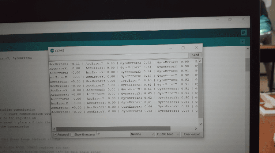
void calculate_IMU_error()
{
// We can call this funtion in the setup section to calculate the accelerometer and gyro data error. From here we will get the error values used in the above equations printed on the Serial Monitor.
// Note that we should place the IMU flat in order to get the proper values, so that we then can the correct values
// Read accelerometer values 200 times
while (c < 200)
{
Wire.beginTransmission(MPU_ADDRESS);
Wire.write(0x3B);
Wire.endTransmission(false);
Wire.requestFrom(MPU_ADDRESS, 6, true);
AccX = (Wire.read() << 8 | Wire.read()) / 16384.0 ;
AccY = (Wire.read() << 8 | Wire.read()) / 16384.0 ;
AccZ = (Wire.read() << 8 | Wire.read()) / 16384.0 ;
// Sum all readings
AccErrorX = AccErrorX + ((atan((AccY) / sqrt(pow((AccX), 2) + pow((AccZ), 2))) * 180 / PI));
AccErrorY = AccErrorY + ((atan(-1 * (AccX) / sqrt(pow((AccY), 2) + pow((AccZ), 2))) * 180 / PI));
c++;
}
//Divide the sum by 200 to get the error value
AccErrorX = AccErrorX / 200;
AccErrorY = AccErrorY / 200;
c = 0;
// Read gyro values 200 times
while (c < 200)
{
Wire.beginTransmission(MPU_ADDRESS);
Wire.write(0x43);
Wire.endTransmission(false);
Wire.requestFrom(MPU_ADDRESS, 6, true);
GyroX = Wire.read() << 8 | Wire.read();
GyroY = Wire.read() << 8 | Wire.read();
GyroZ = Wire.read() << 8 | Wire.read();
// Sum all readings
GyroErrorX = GyroErrorX + (GyroX / 131.0);
GyroErrorY = GyroErrorY + (GyroY / 131.0);
GyroErrorZ = GyroErrorZ + (GyroZ / 131.0);
c++;
}
//Divide the sum by 200 to get the error value
GyroErrorX = GyroErrorX / 200;
GyroErrorY = GyroErrorY / 200;
GyroErrorZ = GyroErrorZ / 200;
// Print the error values on the Serial Monitor
Serial.print("AccErrorX: ");
Serial.print(AccErrorX);
Serial.print(" | AccErrorY: ");
Serial.print(AccErrorY);
Serial.print(" | GyroErrorX: ");
Serial.print(GyroErrorX);
Serial.print(" | GyroErrorY: ");
Serial.print(GyroErrorY);
Serial.print(" | GyroErrorZ: ");
Serial.println(GyroErrorZ);
delay(1000); }


I’ve been browsing online greater than 3 hours lately, but I never found any interesting article like yours. It is pretty value sufficient for me. In my opinion, if all webmasters and bloggers made just right content as you probably did, the web might be a lot more helpful than ever before.