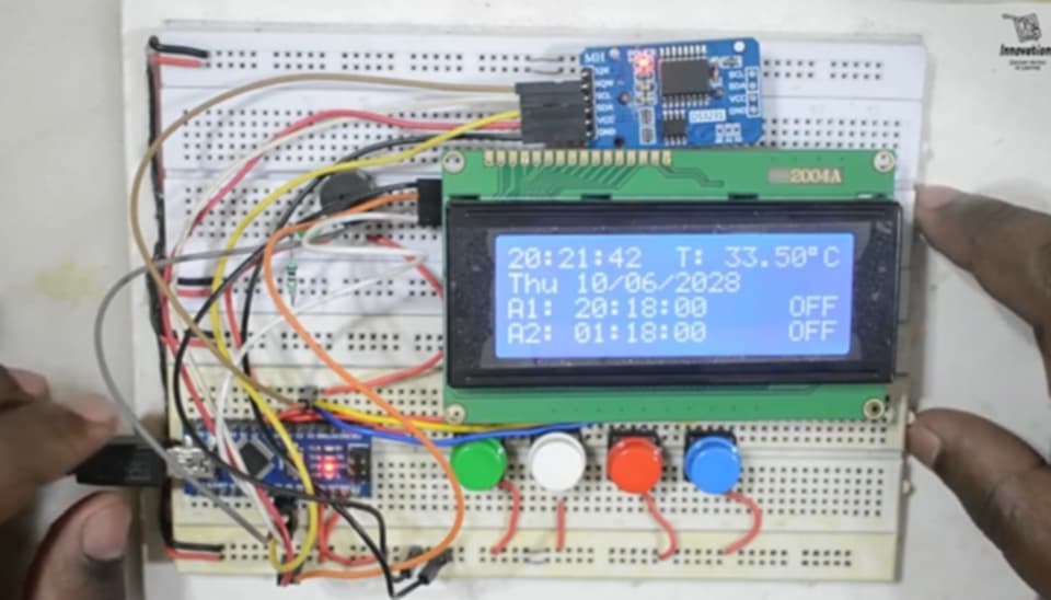
Digital Clock with Arduino, LCD, and RTC Module
In this exciting project, we will use Arduino, a 16×2 LCD display, and a DS3231 RTC (Real-Time Clock) module to build a fully functional digital clock. The clock will allow you to easily set the time and date, with a convenient alarm feature. You will also be able to change the time and date using buttons, and the LCD display will show real-time updates. This project provides a great opportunity to understand Arduino programming and electronic component connections in depth. Let’s dive into how you can create your very own digital clock!
Required Components
For this project, you’ll need the following components:
- Arduino Uno: The microcontroller that will run the program and control other components.
- 16×2 LCD Display: Used to display the time and date.
- DS3231 RTC Module: A highly accurate real-time clock module for maintaining time and date.
- 4 Buttons: To set the time, change values, set the alarm, and toggle the backlight.
- Buzzer: To activate an alarm when the set time is reached.
- Jumper Wires: For making necessary connections.
- Breadboard: For connecting all the components.
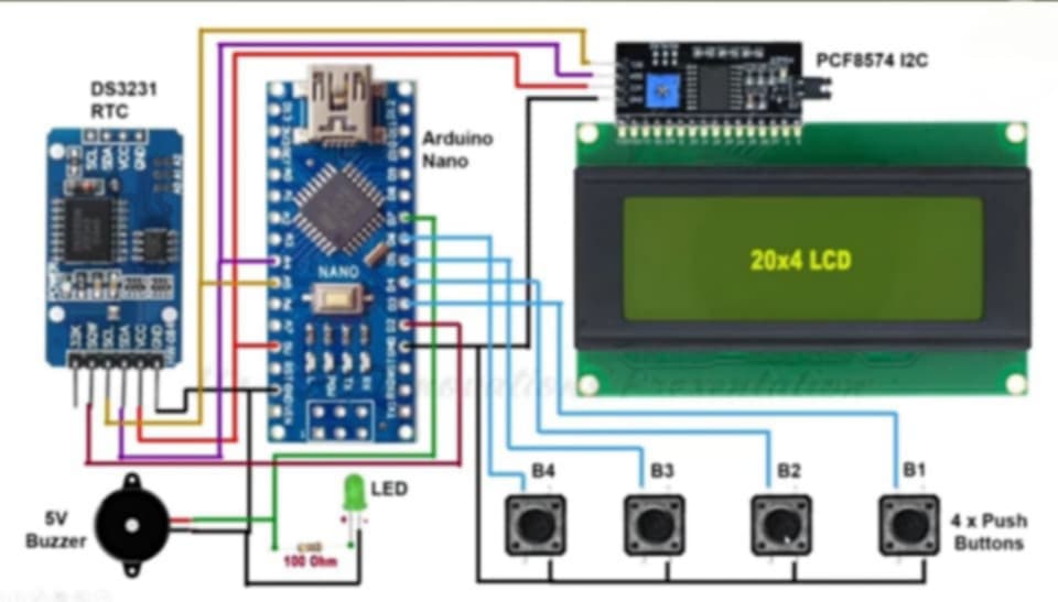
Connections
Follow these connection instructions to set up your components correctly:
LCD Display:
- SDA Pin → Arduino A4 Pin
- SCL Pin → Arduino A5 Pin
DS3231 RTC Module:
- SDA Pin → Arduino A4 Pin
- SCL Pin → Arduino A5 Pin
Buttons:
- Button 1 (Set Time) → Arduino Pin 3
- Button 2 (Change Value) → Arduino Pin 4
- Button 3 (Set Alarm) → Arduino Pin 5
- Button 4 (Backlight Toggle) → Arduino Pin 6
Buzzer:
- Positive Pin → Arduino Pin 7
Daigrams
Code
Now, let’s take a look at the code that will bring everything to life. Once you upload this code to your Arduino, the LCD display will show the current time and date, while allowing you to set and adjust the alarm.
#include <LiquidCrystal_I2C.h>
#include <Wire.h>

LiquidCrystal_I2C lcd(0x3F, 20, 4);

const int button1 = 3;
const int button2 = 4;
const int button3 = 5;
const int button4 = 6;
const int alarm_pin = 7;
bool lcdBacklight = true;

const int buzzerPin = 7;
const int shortToneFreq = 900;
const int longToneFreq = 900;
const int shortDuration = 100;
const int longDuration = 450;
const int shortPause = 50;
const int longPause = 300;

enum State {
  INITIAL_PAUSE,
  SHORT_TONE,
  SHORT_PAUSE,
  LONG_TONE,
  LONG_PAUSE,
};

State currentState = INITIAL_PAUSE;
unsigned long lastEventTime = 0;
int toneCount = 0;
bool alarming = false;

void setup() {
  pinMode(button1, INPUT_PULLUP);
  pinMode(button2, INPUT_PULLUP);
  pinMode(button3, INPUT_PULLUP);
  pinMode(button4, INPUT_PULLUP);
  pinMode(alarm_pin, OUTPUT);
  digitalWrite(alarm_pin, LOW);

  pinMode(buzzerPin, OUTPUT);
  noTone(buzzerPin);

  lcd.init();
  Wire.begin();
  attachInterrupt(digitalPinToInterrupt(2), Alarm, FALLING);
  lcd.clear();
  lcd.backlight();
}

bool alarm1_status, alarm2_status;
char Time[] = "  :  :  ",
     calendar[] = "      /  /20  ",
     alarm1[] = "A1:   :  :00", alarm2[] = "A2:   :  :00",
     temperature[] = "T:   .   C";
byte i, second, minute, hour, day, date, month, year,
     alarm1_minute, alarm1_hour, alarm2_minute, alarm2_hour,
     status_reg;

void Alarm(){
  alarming = HIGH;
}

void DS3231_read(){
  Wire.beginTransmission(0x68);
  Wire.write(0);
  Wire.endTransmission(false);
  Wire.requestFrom(0x68, 7);
  second = Wire.read();
  minute = Wire.read();
  hour = Wire.read();
  day = Wire.read();
  date = Wire.read();
  month = Wire.read();
  year = Wire.read();
}

void alarms_read_display(){
  byte control_reg, temperature_lsb;
  char temperature_msb;
  Wire.beginTransmission(0x68);
  Wire.write(0x08);
  Wire.endTransmission(false);
  Wire.requestFrom(0x68, 11);
  alarm1_minute = Wire.read();
  alarm1_hour = Wire.read();
  Wire.read();
  alarm2_minute = Wire.read();
  alarm2_hour = Wire.read();
  Wire.read();
  control_reg = Wire.read();
  status_reg = Wire.read();
  Wire.read();
  temperature_msb = Wire.read();
  temperature_lsb = Wire.read();
  alarm1_minute = (alarm1_minute >> 4) * 10 + (alarm1_minute & 0x0F);
  alarm1_hour = (alarm1_hour >> 4) * 10 + (alarm1_hour & 0x0F);
  alarm2_minute = (alarm2_minute >> 4) * 10 + (alarm2_minute & 0x0F);
  alarm2_hour = (alarm2_hour >> 4) * 10 + (alarm2_hour & 0x0F);
  alarm1[8] = alarm1_minute % 10 + 48;
  alarm1[7] = alarm1_minute / 10 + 48;
  alarm1[5] = alarm1_hour % 10 + 48;
  alarm1[4] = alarm1_hour / 10 + 48;
  alarm2[8] = alarm2_minute % 10 + 48;
  alarm2[7] = alarm2_minute / 10 + 48;
  alarm2[5] = alarm2_hour % 10 + 48;
  alarm2[4] = alarm2_hour / 10 + 48;
  alarm1_status = bitRead(control_reg, 0);
  alarm2_status = bitRead(control_reg, 1);
  if(temperature_msb < 0){
    temperature_msb = abs(temperature_msb);
    temperature[2] = '-';
  }
  else
    temperature[2] = ' ';
  temperature_lsb >>= 6;
  temperature[4] = temperature_msb % 10 + 48;
  temperature[3] = temperature_msb / 10 + 48;
  if(temperature_lsb == 0 || temperature_lsb == 2){
    temperature[7] = '0';
    if(temperature_lsb == 0) temperature[6] = '0';
    else temperature[6] = '5';
  }
  if(temperature_lsb == 1 || temperature_lsb == 3){
    temperature[7] = '5';
    if(temperature_lsb == 1) temperature[6] = '2';
    else temperature[6] = '7';
  }
  temperature[8] = 223;
  lcd.setCursor(10, 0);
  lcd.print(temperature);
  lcd.setCursor(0, 2);
  lcd.print(alarm1);
  lcd.setCursor(17, 2);
  if(alarm1_status) lcd.print("ON ");
  else lcd.print("OFF");
  lcd.setCursor(0, 3);
  lcd.print(alarm2);
  lcd.setCursor(17, 3);
  if(alarm2_status) lcd.print("ON ");
  else lcd.print("OFF");
}

void calendar_display(){
  switch(day){
    case 1: strcpy(calendar, "Sun   /  /20  "); break;
    case 2: strcpy(calendar, "Mon   /  /20  "); break;
    case 3: strcpy(calendar, "Tue   /  /20  "); break;
    case 4: strcpy(calendar, "Wed   /  /20  "); break;
    case 5: strcpy(calendar, "Thu   /  /20  "); break;
    case 6: strcpy(calendar, "Fri   /  /20  "); break;
    case 7: strcpy(calendar, "Sat   /  /20  "); break;
    default: strcpy(calendar, "Sat   /  /20  ");
  }
  calendar[13] = year % 10 + 48;
  calendar[12] = year / 10 + 48;
  calendar[8] = month % 10 + 48;
  calendar[7] = month / 10 + 48;
  calendar[5] = date % 10 + 48;
  calendar[4] = date / 10 + 48;
  lcd.setCursor(0, 1);
  lcd.print(calendar);
}

void DS3231_display(){
  second = (second >> 4) * 10 + (second & 0x0F);
  minute = (minute >> 4) * 10 + (minute & 0x0F);
  hour = (hour >> 4) * 10 + (hour & 0x0F);
  date = (date >> 4) * 10 + (date & 0x0F);
  month = (month >> 4) * 10 + (month & 0x0F);
  year = (year >> 4) * 10 + (year & 0x0F);
  Time[7] = second % 10 + 48;
  Time[6] = second / 10 + 48;
  Time[4] = minute % 10 + 48;
  Time[3] = minute / 10 + 48;
  Time[1] = hour % 10 + 48;
  Time[0] = hour / 10 + 48;
  calendar_display();
  lcd.setCursor(0, 0);
  lcd.print(Time);
}

void Blink(){
  byte j = 0;
  while(j < 10 && (digitalRead(button1) || i >= 5) && digitalRead(button2) && (digitalRead(button3) || i < 5)){
    j++;
    delay(25);
  }
}

byte edit(byte x, byte y, byte parameter){
  char text[3];
  while(!digitalRead(button1) || !digitalRead(button3));
  while(true){
    while(!digitalRead(button2)){
      parameter++;
      if(((i == 0) || (i == 5)) && parameter > 23)
        parameter = 0;
      if(((i == 1) || (i == 6)) && parameter > 59)
        parameter = 0;
      if(i == 2 && parameter > 31)
        parameter = 1;
      if(i == 3 && parameter > 12)
        parameter = 1;
      if(i == 4 && parameter > 99)
        parameter = 0;
      if(i == 7 && parameter > 1)
        parameter = 0;
      lcd.setCursor(x, y);
      if(i == 7){
        if(parameter == 1)  lcd.print("ON ");
        else                lcd.print("OFF");
      }
      else{
        sprintf(text,"%02u", parameter);
        lcd.print(text);
      }
      if(!digitalRead(button1)) break;
      delay(20);
    }
  }
  return parameter;
}
Code Explanation
Library Imports:
#include <Wire.h>
#include <LiquidCrystal_I2C.h>
#include <DS3231.h>
These libraries are essential for our project:
- Wire.h: Used for I2C communication between Arduino and connected modules.
- LiquidCrystal_I2C.h: Allows easy control of the LCD display using I2C.
- DS3231.h: Enables communication with the DS3231 RTC module to fetch the time and date.
Variable Declarations:
DS3231 rtc(SDA, SCL);
LiquidCrystal_I2C lcd(0x27, 16, 2);
Here, we create instances for the RTC and LCD to handle the respective modules’ functionalities.
setup() Function:
In the setup function, we define the pin modes for the buttons and buzzer. We also initialize the LCD and RTC modules. The LCD will display the message “Digital Clock” for 2 seconds as a startup display.
loop() Function:
This function repeatedly fetches the current time and date from the RTC module and displays it on the LCD. The time and date will update every second, keeping the display in sync with the current time.
Displaying Time and Date:
lcd.setCursor(0, 0);
lcd.print("Time: ");
lcd.print(hour);
lcd.print(":");
lcd.print(minute);
lcd.print(":");
lcd.print(second);
The lcd.setCursor() and lcd.print() functions are used to show the current time and date on the LCD at specific positions.
Conclusion
Once you upload the code and connect the components correctly, the LCD display will show the current time and date, which will update every second. This project serves as a foundation for understanding how to work with real-time clocks, LCDs, and interactive buttons. You can later add features like setting time, changing values, and activating alarms for a more advanced clock system.
Happy tinkering with your digital clock project!


