Create a Simple RFID Project: Step-by-Step Guide
Radio-Frequency Identification (RFID) technology is one of the most effective tools used today for secure data reading, identification, and management in a variety of systems and devices. This technology allows devices to read unique data from RFID-enabled cards or tags wirelessly, making it a popular choice for applications such as access control, inventory tracking, and automation.
In this comprehensive tutorial, we will guide you through the process of creating a simple yet powerful project using an Arduino and an RFID reader module. This project will focus on building an access control system where the Arduino, in conjunction with the RFID reader, will verify whether a card or tag is authorized to gain access. Upon successful verification, it will trigger appropriate outputs such as activating LEDs to indicate access granted or denied.
This hands-on project will not only enhance your understanding of RFID technology but will also give you practical experience in building a functional and secure system using Arduino. Whether you’re a beginner or an enthusiast looking to explore the capabilities of RFID, this guide will provide you with step-by-step instructions to successfully complete the project.
Required Components
You will need the following components for this project:
- Arduino UNO – 1
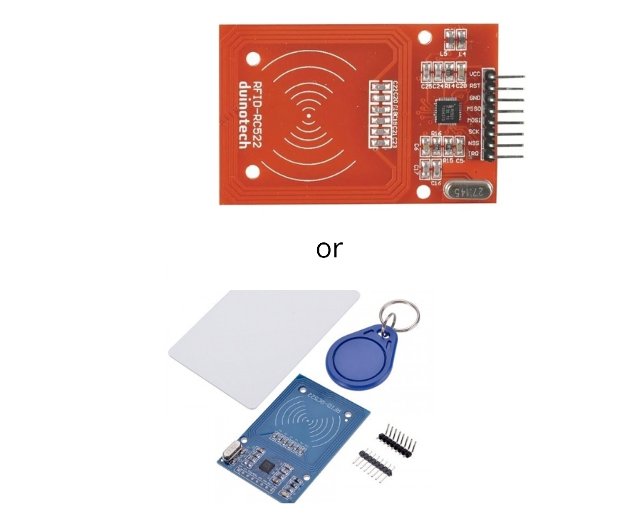
- RFID Reader (MFRC522) – 1
- Green LED – 1
- Red LED – 1
- 220-ohm Resistors – 2
- Breadboard – 1
- Jumper Wires – 10
Project Goal
Through this project, we aim to:
- Understand how an RFID reader works.
- Interface an RFID reader with Arduino.
- Differentiate between authorized and unauthorized access.
How RFID Works
An RFID system consists of three main parts:
- Scanning Antenna
- Transceiver
- Transponder
An RFID reader combines a scanning antenna and a transceiver. It is a network-connected device that can be portable or fixed. The RFID reader transmits a signal via radio waves to activate the tag. Once activated, the tag sends its data back to the reader’s antenna, where it is processed and translated.
RFID Connections
Here are the pin connections for the RFID reader and other components:
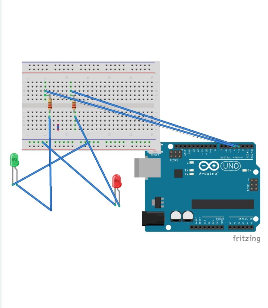
LED Connections
- Green LED:
- Positive pin: Digital pin 4 on Arduino
- Negative pin: GND
- Red LED:
- Positive pin: Digital pin 3 on Arduino
- Negative pin: GND

RFID Reader Connections
- VCC: Connect to 3.3V (Do not connect to 5V, as it may damage the board.)
- RST: D9
- GND: GND
- MISO: D12
- MOSI: D11
- SCK: D13
- SDA/NSS: D10
Code Explanation
The following code allows the Arduino to interface with the RFID reader and verify the UID of the card or tag:
#include <SPI.h>
#include <MFRC522.h>

#define SS_PIN 10
#define RST_PIN 9
MFRC522 mfrc522(SS_PIN, RST_PIN);   // Create MFRC522 instance

void setup()
{
  pinMode(4, OUTPUT); // Green LED
  pinMode(3, OUTPUT); // Red LED
  Serial.begin(9600); // Start Serial Communication
  SPI.begin();        // Initialize SPI bus
  mfrc522.PCD_Init(); // Initialize MFRC522
  Serial.println("Place your card near the reader...");
}

void loop()
{
  // Check for new cards
  if (!mfrc522.PICC_IsNewCardPresent()) {
    return;
  }

  // Select one of the cards
  if (!mfrc522.PICC_ReadCardSerial()) {
    return;
  }

  // Show UID
  Serial.print("UID tag: ");
  String content = "";
  for (byte i = 0; i < mfrc522.uid.size; i++)
  {
    Serial.print(mfrc522.uid.uidByte[i] < 0x10 ? " 0" : " ");
    Serial.print(mfrc522.uid.uidByte[i], HEX);
    content.concat(String(mfrc522.uid.uidByte[i] < 0x10 ? " 0" : " "));
    content.concat(String(mfrc522.uid.uidByte[i], HEX));
  }
  Serial.println();

  content.toUpperCase();

  // Verify UID
  if (content.substring(1) == "53 F7 CE 18") // Replace with your card’s UID
  {
    digitalWrite(4, HIGH); // Green LED ON
    digitalWrite(3, LOW);  // Red LED OFF
    Serial.println("Authorized Access");
    delay(3000);
  }
  else
  {
    digitalWrite(4, LOW);  // Green LED OFF
    digitalWrite(3, HIGH); // Red LED ON
    Serial.println("Access Denied");
    delay(3000);
  }
}
Key Code Details
- Library Inclusion:
TheSPI.handMFRC522.hlibraries are used for RFID functionality. - Pin Definitions:
- SS_PIN (SDA/NSS): D10
- RST_PIN: D9
- UID Verification:
The UID is a unique identifier for every RFID card or tag. View the UID in the Serial Monitor and update the code with your card’s UID.
Steps to Build the Project
To successfully complete this RFID-based project, follow the steps outlined below carefully. Each step is crucial for the proper functioning of the system:
- Connect All Components to the Breadboard as Described
Begin by assembling your circuit on the breadboard according to the wiring diagram provided. Ensure that the RFID reader, LEDs, resistors, and jumper wires are securely connected to the Arduino board. Double-check the connections for accuracy, especially for the RFID reader, as incorrect wiring can damage the module. - Write the Code in the Arduino IDE and Upload It to the Arduino Board
Open the Arduino IDE on your computer and paste the provided code into the editor. After ensuring that all required libraries (e.g., SPI and MFRC522) are installed, compile the code. Once the code compiles successfully, connect your Arduino board to the computer via USB and upload the program to the board. - Check the Serial Monitor to View the UID of Your Card
Open the Serial Monitor in the Arduino IDE after uploading the code. Place your RFID card or tag near the reader. The Serial Monitor will display the unique UID (Unique Identifier) of the card. This UID will be used to differentiate between authorized and unauthorized cards or tags. - Use the Verified UID in the Code and Test the Project
Copy the UID displayed in the Serial Monitor and replace the placeholder UID in the code with the actual UID of your authorized card. Re-upload the updated code to the Arduino board. Test the project by placing both authorized and unauthorized cards near the RFID reader to observe the responses.
Benefits of This Project
Building this project offers several advantages, including:
- Easy Implementation of an Access Control System
This project provides a straightforward way to create a functional access control system using readily available components. The simplicity of the design makes it ideal for beginners while still being effective in real-world applications. - Fundamental Understanding of RFID Technology
Through this project, you will gain a deeper understanding of how RFID technology works, including its components, functionality, and integration with microcontrollers like Arduino. This knowledge can be applied to more advanced projects and systems in the future. - Practical Use Case for Enhancing Security
This project demonstrates a practical application of RFID for enhancing security. Whether it’s controlling access to a restricted area or verifying identity, this system showcases how RFID can be effectively used for secure operations.
Conclusion
This RFID-based project demonstrates how you can use an RFID reader module with Arduino to create a simple yet powerful access control system. Once completed, this system can be adapted for various purposes, such as managing access to doors, tracking attendance, or implementing other security measures.
By following the steps outlined in this guide, you not only build a functional system but also gain valuable insights into RFID technology and its real-world applications. This project is a stepping stone to exploring the vast potential of automation and security systems in your future projects!


Thanks for sharing excellent informations. Your website is very cool. I am impressed by the details that you¦ve on this blog. It reveals how nicely you perceive this subject. Bookmarked this web page, will come back for more articles. You, my friend, ROCK! I found just the info I already searched everywhere and simply couldn’t come across. What a perfect web-site.