
NRF24L01-Based Button State Transmission and Receiver System
Components Required
- Arduino Nano – 2 units
- NRF24L01 Module – 2 units
- Push Button – 1 unit
- LED – 1 unit
- 220Ω Resistor – 1 unit
- Breadboard and jumper wires
How It Works
- Transmitter: Sends the push button’s state (HIGH/LOW).
- Receiver: Receives the transmitted data and displays the state using an LED.
Circuit Diagram
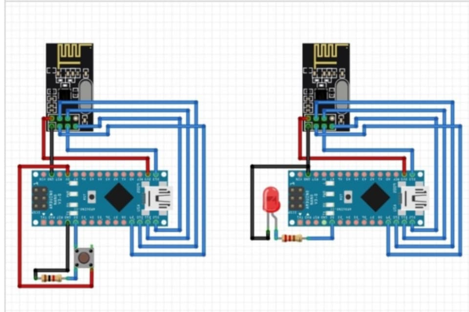
Transmitter:
- NRF24L01 Connections:
- VCC → Arduino 3.3V
- GND → Arduino GND
- CE → Pin 9
- CSN → Pin 10
- SCK → Pin 13
- MOSI → Pin 11
- MISO → Pin 12
- Button Connection:
- One terminal → Pin 2
- Other terminal → GND (with pull-down resistor)
Receiver:
- NRF24L01 Connections:
- VCC → Arduino 3.3V
- GND → Arduino GND
- CE → Pin 9
- CSN → Pin 10
- SCK → Pin 13
- MOSI → Pin 11
- MISO → Pin 12
- LED Connection:
- Anode → Pin 3 (via resistor)
- Cathode → GND
Code
Transmitter Code
#include <SPI.h>
#include <nRF24L01.h>
#include <RF24.h>

RF24 radio(9, 10);  // CE, CSN pins
const byte address[6] = "00001";  // Communication address
int button_pin = 2;  // Button pin
boolean button_state = 0;

void setup()
{
  pinMode(button_pin, INPUT);
  radio.begin();
  radio.openWritingPipe(address);
  radio.setPALevel(RF24_PA_MIN);
  radio.stopListening();
}

void loop()
{
  button_state = digitalRead(button_pin);
  if (button_state == HIGH)
  {
    const char text[] = "Your Button State is HIGH";
    radio.write(&text, sizeof(text));
  }
  else
  {
    const char text[] = "Your Button State is LOW";
    radio.write(&text, sizeof(text));
  }
  delay(1000);
}
Receiver Code
#include <SPI.h>
#include <nRF24L01.h>
#include <RF24.h>

RF24 radio(9, 10);  // CE, CSN pins
const byte address[6] = "00001";  // Communication address
int led_pin = 3;  // LED pin
boolean button_state;

void setup()
{
  pinMode(led_pin, OUTPUT);
  radio.begin();
  radio.openReadingPipe(0, address);
  radio.setPALevel(RF24_PA_MIN);
  radio.startListening();
}

void loop()
{
  if (radio.available())
  {
    radio.read(&button_state, sizeof(button_state));
    if (button_state == HIGH)
    {
      digitalWrite(led_pin, HIGH);  // Turn LED ON
    }
    else
    {
      digitalWrite(led_pin, LOW);  // Turn LED OFF
    }
  }
}
Step-by-Step Setup
1. Hardware Setup
- Transmitter: Connect the button and NRF24L01 module as per the diagram.
- Receiver: Connect the LED and NRF24L01 module.
- Make sure all pin connections are accurate as shown in the diagram.
2. Software Setup
- Open Arduino IDE.
- Install RF24 Library:
- Go to Sketch > Include Library > Manage Libraries, search for “RF24,” and install it.
- Upload the transmitter code to one Arduino board.
- Upload the receiver code to the other Arduino board.
3. Power and Testing
- Provide 3.3V power to both Arduino boards.
- Press the push button and observe the LED’s behavior on the receiver.
- Check the transmitted messages on the Serial Monitor if needed.
Range and Notes
- Range: Standard NRF24L01 modules have a range of 20–30 meters indoors. Using the NRF24L01-PA-LNA module with an antenna can extend the range to over 1 kilometer (outdoors).
- Ensure the module is powered at 3.3V as it cannot handle 5V.
- For stable communication, place the modules where signal interference is minimal.
This project is highly suitable for remote control systems, robotics, and home automation applications.


1 thought on “Building an NRF24L01 Wireless Communication System with Arduino”