
Arduino and MAX7219 Dot Matrix Display: A Complete Guide
Dot matrix displays, also known as LED matrix displays, are widely used by Arduino enthusiasts for various display applications. These displays allow users to showcase text, numbers, and even small graphical elements in an efficient and visually appealing manner. They are commonly found in digital billboards, scrolling message boards, and other electronic display systems.
One of the most efficient ways to control a dot matrix display with an Arduino is by using the MAX7219 LED driver chip. This powerful integrated circuit simplifies the process of controlling multiple LEDs by reducing the number of pins required for communication. With the MAX7219, you can easily manage one or even multiple dot matrix displays in a daisy-chained configuration, allowing for larger and more complex visual outputs.
In this post, we will take an in-depth look at the MAX7219 module, exploring its features, working principle, and how it can be integrated with an Arduino. We will also go through a step-by-step guide on connecting the module, writing code, and implementing scrolling text or animations on the display. Whether you’re a beginner or an experienced Arduino user, this guide will help you unlock the full potential of MAX7219-powered dot matrix displays for your projects.
MAX7219 Module Overview
The MAX7219 module is a popular choice for controlling LED matrix displays, and it comes in different variations. Among them, two widely used types are the generic MAX7219 module and the FC-16 module. While both serve the same fundamental purpose, there are slight differences in their design and pin configuration, making it essential to choose the right module based on your project requirements.
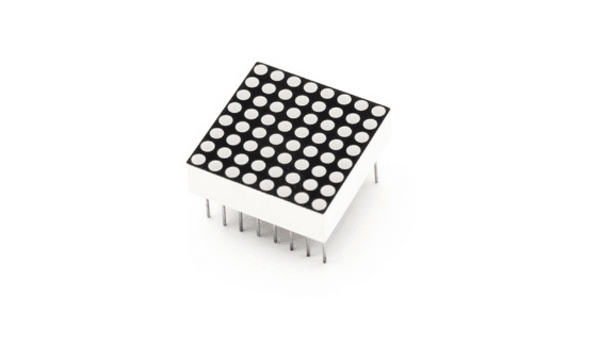
A standard MAX7219 breakout board consists of an 8×8 dot matrix LED display and a MAX7219 LED driver chip. This combination allows for efficient control of 64 individual LEDs while requiring only a few connections to an Arduino or other microcontrollers. The MAX7219 takes care of multiplexing, current limiting, and refreshing the display, which significantly reduces the complexity of managing multiple LEDs manually.
One of the key advantages of using a MAX7219 module is its ability to daisy-chain multiple displays. By linking multiple MAX7219 modules together, you can create long scrolling text displays, graphical animations, or even custom-designed visual effects. The communication between the Arduino and the MAX7219 module is handled via Serial Peripheral Interface (SPI), which allows fast and efficient data transmission with minimal wiring.
In the next sections, we will explore the structure and functionality of the MAX7219 module, its pinout, wiring connections, and how you can program it using an Arduino to display static or scrolling text, numbers, and custom patterns.
Introduction to MAX7219 Module
The MAX7219 chip is a popular solution for using dot matrix displays with Arduino. It can control LEDs through serial data commands and allows chaining multiple displays to create a large screen.
Dot Matrix Display
- Typically consists of an 8×8 matrix with 64 LEDs.
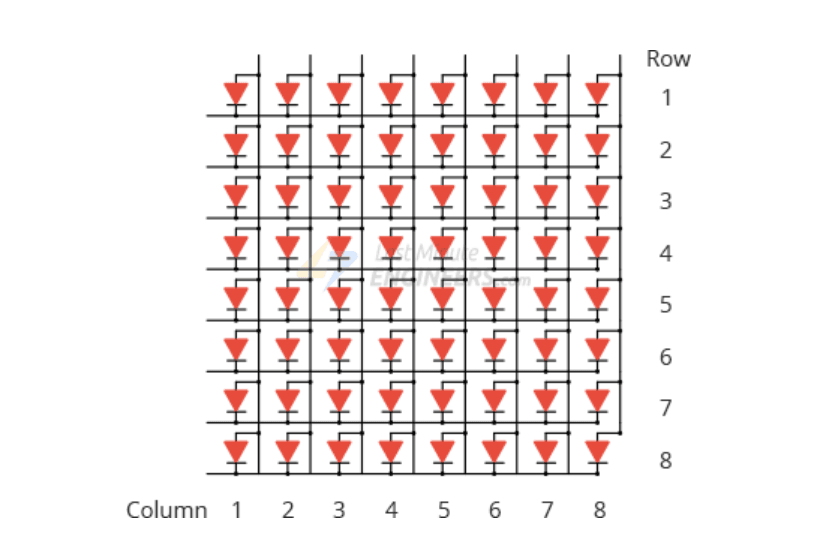
- Has a 16-pin connection, where 8 pins control the rows and 8 control the columns.
- Uses multiplexing technology for operation.
An 8×8 dot matrix display typically has 16 pins, 8 for each row and 8 for each column. All rows and columns are wired together in order to reduce the number of pins. If this were not the case, an 8×8 dot matrix display would require 65 pins, one for each LED and one for a common anode or common cathode connector. By connecting rows and columns, only 16 pins are needed to control the entire matrix. This technique of controlling a large number of LEDs with fewer pins is referred to as Multiplexing.
MAX7219 Chip
- Automatically handles multiplexing.
- Has an 800 Hz refresh rate, ensuring stable display.
- Includes a power-saving mode to turn off LEDs when not needed.
- Uses an SPI interface, requiring only three data pins for control.
- Supports chaining multiple modules for a larger display.
MAX7219 Module Pinout
Input Connector:
- VCC → 5V power supply
- GND → Ground
- DIN → Data input (Connect to any digital pin of Arduino)
- CS/LOAD → Chip select
- CLK → Clock pin
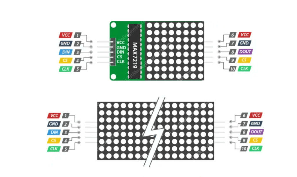
Output Connector (For chaining multiple modules):
- VCC → Connect to the next module’s VCC
- GND → Connect to the next module’s GND
- DOUT → Connect to the next module’s DIN
- CS/LOAD → Connect to the next module’s CS/LOAD
- CLK → Connect to the next module’s CLK
Library Installation for the MAX7219 Module
Controlling the MAX7219 module can be quite complex, but with the help of the MD Parola library, we can simplify the process. This library hides many of the complexities involved in controlling the MAX7219, making it easy to use the module with simple commands.
Here’s how you can install the necessary libraries to get started:
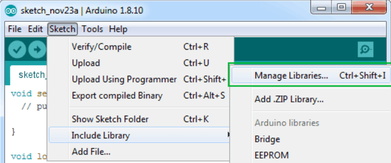
Open the Library Manager:
Navigate to the Arduino IDE and go to Sketch > Include Library > Manage Libraries…. This will open the Library Manager window. Wait for the Library Manager to download the library index and update the list of installed libraries.
Search for the MD_MAX72XX Library:
In the search bar of the Library Manager, type ‘max72xx’ to filter the list of libraries. You should see MD_MAX72XX by MajicDesigns in the search results.
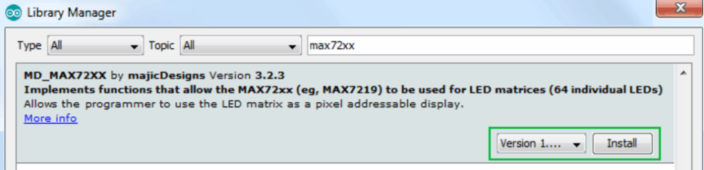
- Install the MD_MAX72XX Library:
Click on MD_MAX72XX and then click on the Install button. This library is a hardware-specific library that helps with low-level functions for controlling the MAX7219. You will need this library in order to interface with the MAX7219 hardware properly. - Install the MD_Parola Library:
The MD_Parola library works in conjunction with the MD_MAX72XX library. While the MD_MAX72XX handles the low-level communication with the hardware, MD_Parola provides the higher-level functionality, such as creating text animations like scrolling and sprite effects. To install it, simply search for ‘MD_Parola’ in the Library Manager and click Install.
Connecting MAX7219 with Arduino
Required Components:
- Arduino UNO
- MAX7219 Dot Matrix Module
- Jumper Wires
- External Power Supply (for larger displays)
Wiring Diagram:
| MAX7219 | Arduino UNO |
|---|---|
| VCC | 5V |
| GND | GND |
| DIN | 11 (MOSI) |
| CS/LOAD | 10 (SS) |
| CLK | 13 (SCK) |
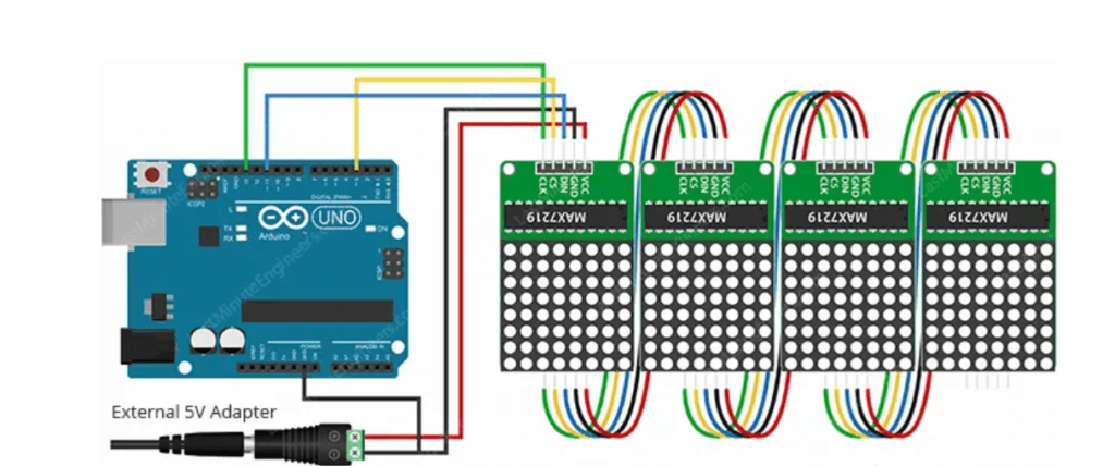
For multiple displays: Connect the DOUT pin of the first module to the DIN pin of the next module.
Arduino Code Explanation for Controlling MAX7219 LED Matrix Display
This code is designed to display text on an 8×32 LED matrix controlled by the MAX7219 module using the MD_Parola and MD_MAX72XX libraries. Below is a step-by-step explanation of how the code works.
1. Including Required Libraries
#include <MD_Parola.h>
#include <MD_MAX72xx.h>
#include <SPI.h>- MD_Parola.h → This library provides high-level functions for text display and animations.
- MD_MAX72xx.h → This is a hardware-specific library that directly communicates with the MAX7219 module.
- SPI.h → The MAX7219 module communicates with the Arduino using the SPI (Serial Peripheral Interface) protocol, which is handled by this library.
2. Defining Hardware Type
#define HARDWARE_TYPE MD_MAX72XX::FC16_HW
//#define HARDWARE_TYPE MD_MAX72XX::GENERIC_HW- The
HARDWARE_TYPEdefines the type of MAX7219 module being used. - FC16_HW: Used for blue PCB modules with an SMD MAX7219 IC.
- GENERIC_HW: Used for green PCB modules with a through-hole MAX7219 IC.
- The
#define HARDWARE_TYPE MD_MAX72XX::FC16_HWline ensures that the FC16 hardware type is selected. - If you are using the GENERIC_HW module, uncomment
#define HARDWARE_TYPE MD_MAX72XX::GENERIC_HWand comment out#define HARDWARE_TYPE MD_MAX72XX::FC16_HW.
3. Defining Display Configuration
#define MAX_DEVICES 4
#define CS_PIN 3- MAX_DEVICES: Specifies the number of 8×8 LED matrices connected in series.
- A single MAX7219 chip controls one 8×8 matrix.
- If you have a 4-module 8×32 LED display, set this to
4.
- CS_PIN: The Chip Select (CS) pin of the MAX7219 module is connected to Arduino pin 3.
4. Creating the Display Object
MD_Parola myDisplay = MD_Parola(HARDWARE_TYPE, CS_PIN, MAX_DEVICES);
MD_Parola myDisplayinitializes a display object namedmyDisplaythat controls the MAX7219 matrix.- This object allows us to control text alignment, brightness, and other display properties.
5. Setup Function (Runs Once)
void setup() {
	// Initialize the object
	myDisplay.begin();

	// Set the intensity (brightness) of the display (0-15)
	myDisplay.setIntensity(0);

	// Clear the display
	myDisplay.displayClear();
}
myDisplay.begin();→ Initializes the display.myDisplay.setIntensity(0);→ Sets the brightness level of the display.- The value can be between
0(dim) and15(bright).
- The value can be between
myDisplay.displayClear();→ Clears any previous text displayed on the matrix.
6. Loop Function (Runs Continuously)
void loop() {
	myDisplay.setTextAlignment(PA_LEFT);
	myDisplay.print("Left");
	delay(2000);

	myDisplay.setTextAlignment(PA_CENTER);
	myDisplay.print("Center");
	delay(2000);

	myDisplay.setTextAlignment(PA_RIGHT);
	myDisplay.print("Right");
	delay(2000);

	myDisplay.setTextAlignment(PA_CENTER);
	myDisplay.setInvert(true);
	myDisplay.print("Invert");
	delay(2000);

	myDisplay.setInvert(false);
	myDisplay.print(1234);
	delay(2000);
}
Displaying Text with Different Alignments
- Left-Aligned Text
myDisplay.setTextAlignment(PA_LEFT); myDisplay.print("Left"); delay(2000);- The text
"Left"is displayed left-aligned on the matrix for 2 seconds.
- The text
- Center-Aligned Text cppCopyEdit
myDisplay.setTextAlignment(PA_CENTER); myDisplay.print("Center"); delay(2000);- The text
"Center"is displayed centered on the matrix for 2 seconds.
- The text
- Right-Aligned Text cppCopyEdit
myDisplay.setTextAlignment(PA_RIGHT); myDisplay.print("Right"); delay(2000);- The text
"Right"is displayed right-aligned on the matrix for 2 seconds.
- The text
Inverting the Display
- Inverted Text cppCopyEdit
myDisplay.setTextAlignment(PA_CENTER); myDisplay.setInvert(true); myDisplay.print("Invert"); delay(2000);- The text
"Invert"is displayed with inverted colors (black text on a lit background).
- The text
- Reverting to Normal Display cppCopyEdit
myDisplay.setInvert(false); myDisplay.print(1234); delay(2000);- The display returns to normal mode and shows the number 1234 for 2 seconds.
Summary
- Displays different text alignments (Left, Center, Right).
- Demonstrates text inversion mode.
- Controls brightness and clears display.
- Uses a 4-module 8×32 LED display controlled by the MAX7219 driver.
Arduino cod
#include <MD_Parola.h>
#include <MD_MAX72xx.h>
#include <SPI.h>

// Uncomment according to your hardware type
#define HARDWARE_TYPE MD_MAX72XX::FC16_HW
//#define HARDWARE_TYPE MD_MAX72XX::GENERIC_HW

// Defining size, and output pins
#define MAX_DEVICES 4
#define CS_PIN 3

// Create a new instance of the MD_Parola class with hardware SPI connection
MD_Parola myDisplay = MD_Parola(HARDWARE_TYPE, CS_PIN, MAX_DEVICES);

void setup() {
	// Intialize the object
	myDisplay.begin();

	// Set the intensity (brightness) of the display (0-15)
	myDisplay.setIntensity(0);

	// Clear the display
	myDisplay.displayClear();
}

void loop() {
	myDisplay.setTextAlignment(PA_LEFT);
	myDisplay.print("Left");
	delay(2000);

	myDisplay.setTextAlignment(PA_CENTER);
	myDisplay.print("Center");
	delay(2000);

	myDisplay.setTextAlignment(PA_RIGHT);
	myDisplay.print("Right");
	delay(2000);

	myDisplay.setTextAlignment(PA_CENTER);
	myDisplay.setInvert(true);
	myDisplay.print("Invert");
	delay(2000);

	myDisplay.setInvert(false);
	myDisplay.print(1234);
	delay(2000);}


Can I just say what a relief to find someone who actually knows what theyre talking about on the internet. You definitely know how to bring an issue to light and make it important. More people need to read this and understand this side of the story. I cant believe youre not more popular because you definitely have the gift.